Complete text and all illustrations for monograph [6/2e] by Dr Jan Pajak,
"Devices for the Telekinetic Extraction of Energy from the
Environment" (Copyright 1993, ISBN 0-9597946-5-4).
Notices:
(1) In order to download to your computer text of any of volumes listed below,
or in order to see/download any illustraction, just click
on underlined description chosen from the list below!
(2) Note that in order to neutralize effects of the continuous sabotage
of monograph [6e] by evil parasites from UFOs, monograph [6e] is also downloadable
from several further Web sites (look for Text [6e] in "Menu 3"). Thus if something
refuses to download from this page, try to download it from another location.
(3) Almost all illustrations used in this monograph [6e] are also used in monographs [1/4] and [1e]. Thus if here these come out unclear, they can also be seen in [1/4] or [1e].
(4) For further instructions see the end of this Web page.
English version of [6e]:
Part A: Text of the English language version of
monograph [6], compressed from WORD XP.
The full version of English monograph [6e] consists of
one volume downloadable from this section. Here it is:
Compressed version of the entire text of [6/2]. The content of this monograph is as explained in previous item.
Polish version of [6/2]:
Part B: Text of the Polish laguage version of monograph [6]
compressed to ZIP from WORD XP (with Polish letters).
Tekst monografii [6/2], ZIP z WORDa XP (7/3/04)
Part C: Ilustrations for both versions of monograph [6]
(i.e. for English and Polish), in formats *.gif or *.jpg.
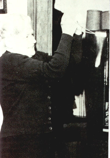 [6/2p] Rys. 1. [6/2p] Rys. 1.
[6/2e] Figure 1: A photo of the extraction glow emmited by a diving rod. This emmision of the white light takes place because of the Telekinetic Effect works as a reversal of friction and extract heat from the environment.
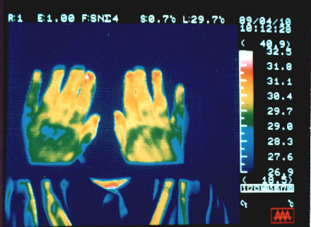 [6/2p] Rys. 2-A. [6/2p] Rys. 2-A.
[6/2e] Figure 2-A: A telekinetic temperature drop on the hand of a healer (at 10:12). It also occurs because the telekinesis which a healer generates, extracts heat from the environment.
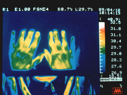 [6/2p] Rys. 2-B. [6/2p] Rys. 2-B.
[6/2e] Figure 2-B: A telekinetic temperature drop on the hand of a healer (at 10:14).
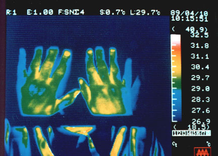 [6/2p] Rys. 2-C. [6/2p] Rys. 2-C.
[6/2e] Figure 2-C: A telekinetic temperature drop on the hand of a healer (at 10:15).
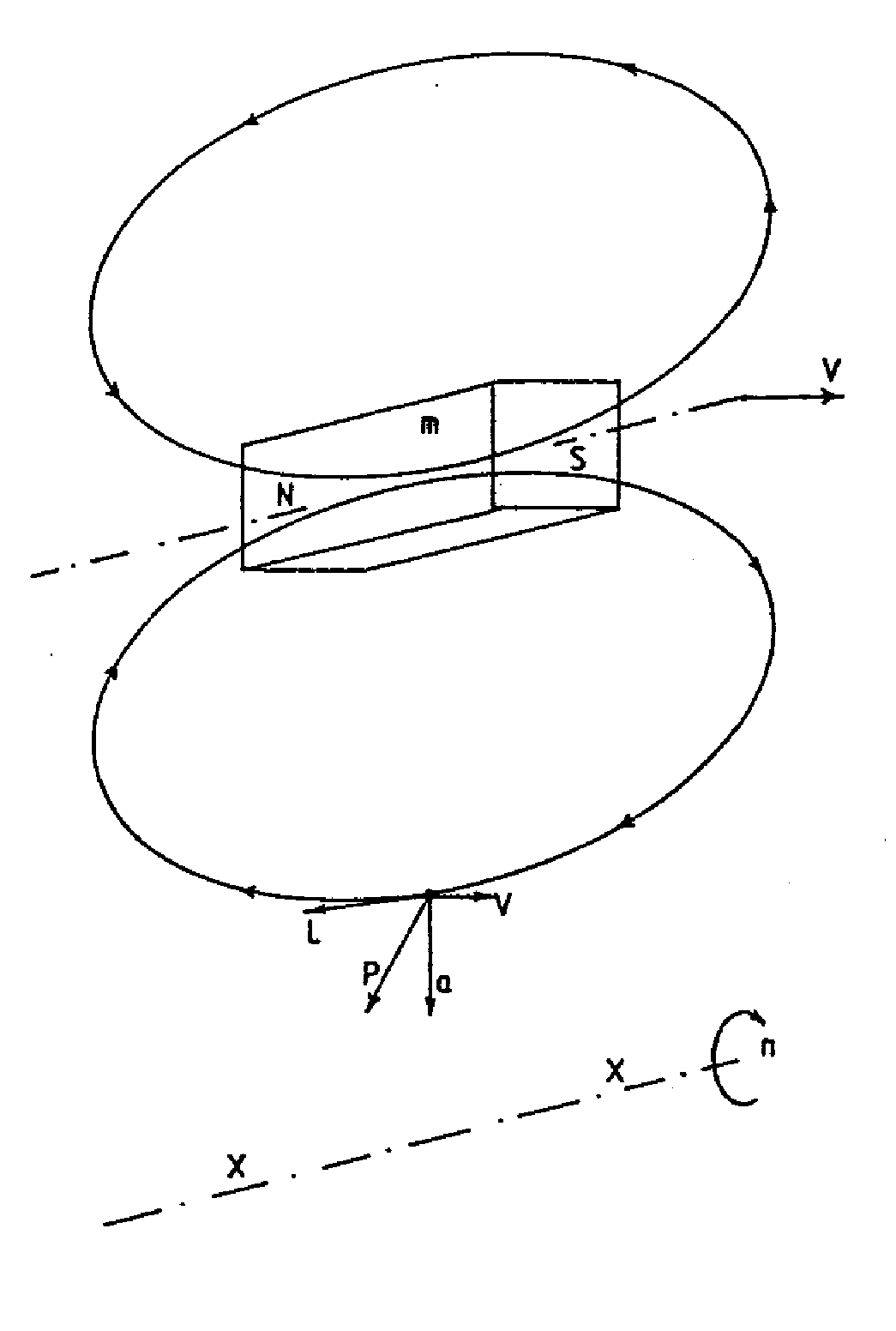 [6/2p] Rys. 3. [6/2p] Rys. 3.
[6/2e] Figure 3: An elementary Telekinetic Effect.
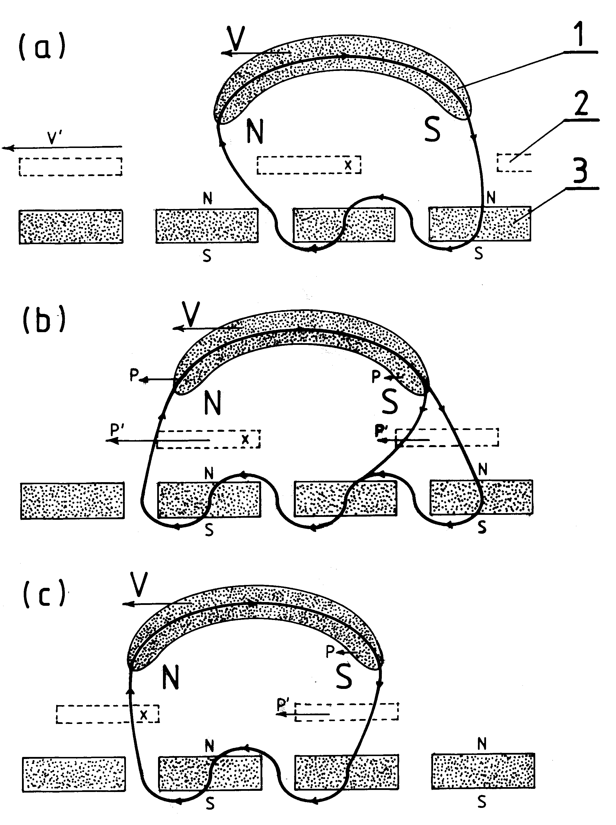 [6/2p] Rys. 4. [6/2p] Rys. 4.
[6/2e] Figure 4: The operation of the Johnston telekinetic motor.
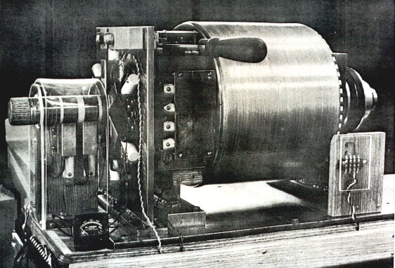 [6/2p] Rys. 5. [6/2p] Rys. 5.
[6/2e] Figure 5: A photo of the telekinetic generator called N-Machine.
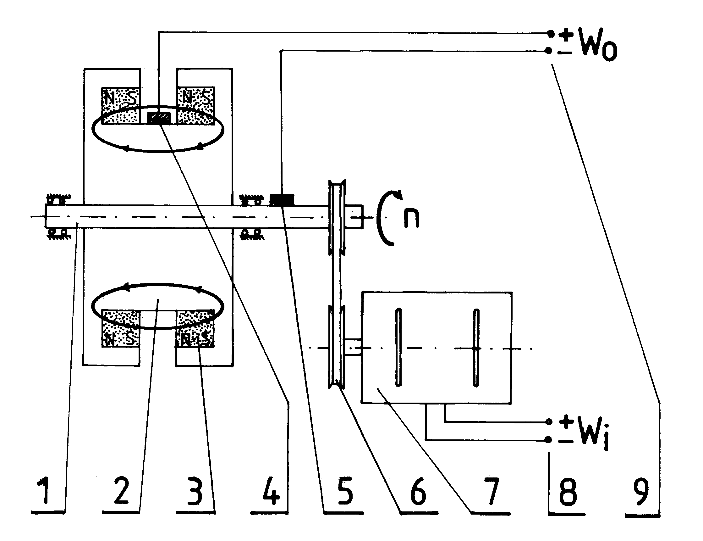 [6/2p] Rys. 6. [6/2p] Rys. 6.
[6/2e] Figure 6: The design and operation of N-Machine.
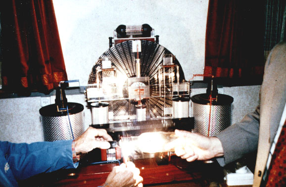 [6/2p] Rys. 7. [6/2p] Rys. 7.
[6/2e] Figure 7: A photograph of a telekinetic free energy device called Influenzmaschine.
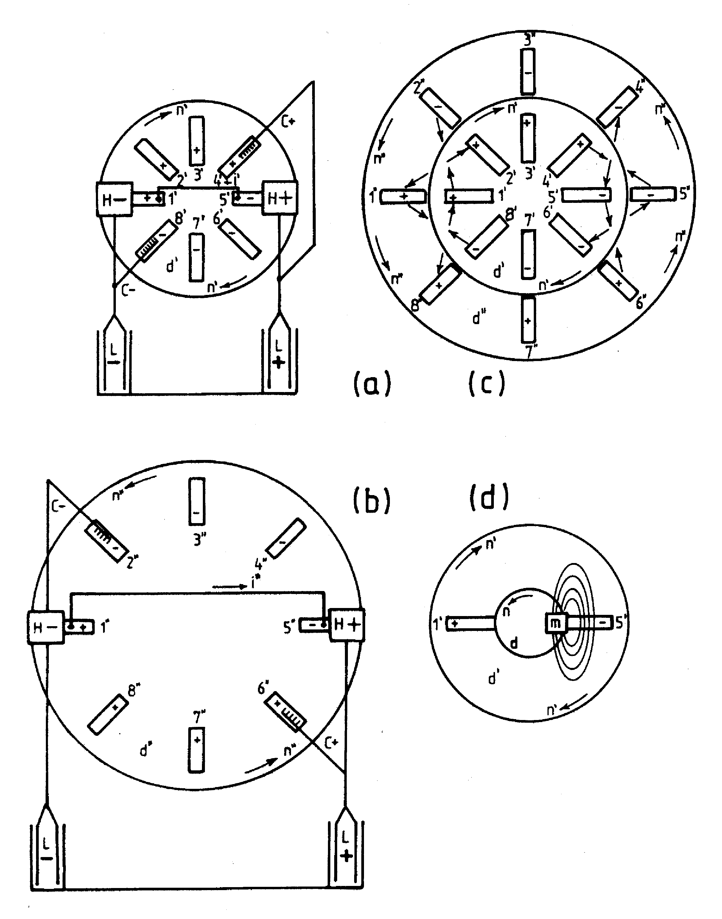 [6/2p] Rys. 8. [6/2p] Rys. 8.
[6/2e] Figure 8: The operation of Influenzmaschine.
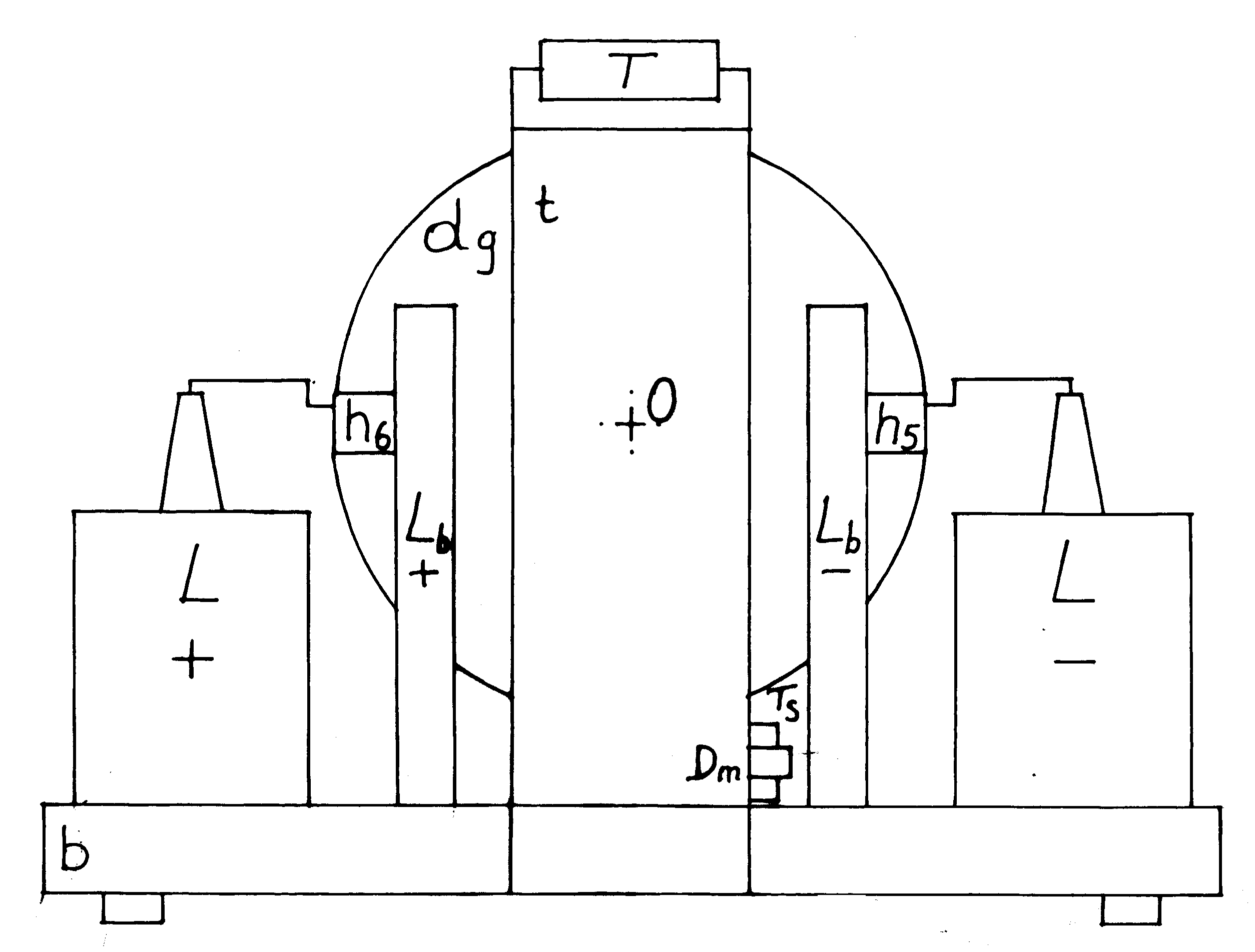 [6/2p] Rys. 9(a). [6/2p] Rys. 9(a).
[6/2e] Figure 9 (a): The design and components of telekinetic Influenzmaschine - back view.
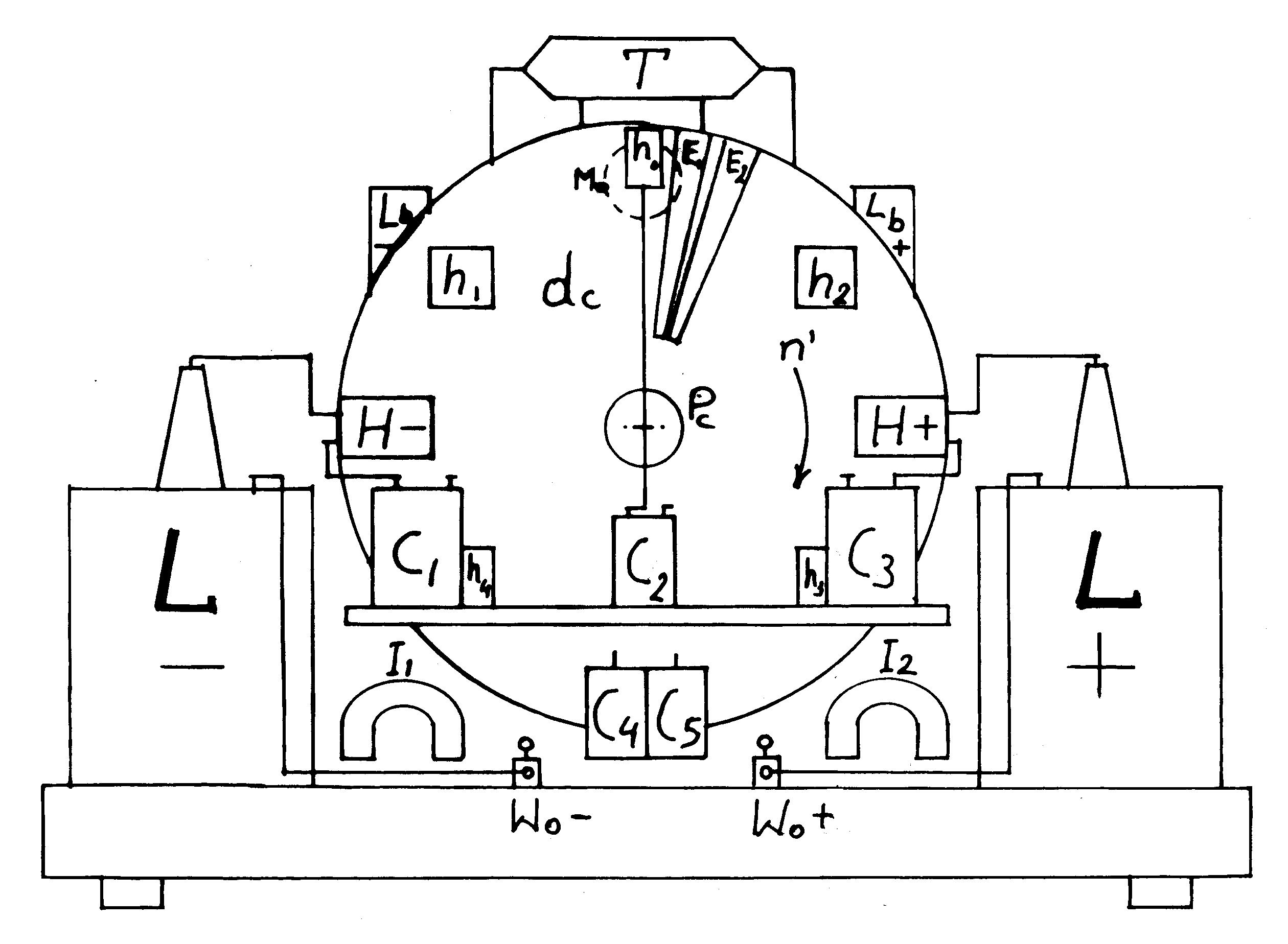 [6/2p] Rys. 9(b). [6/2p] Rys. 9(b).
[6/2e] Figure 9 (b): Telekinetic Influenzmaschine - front view.
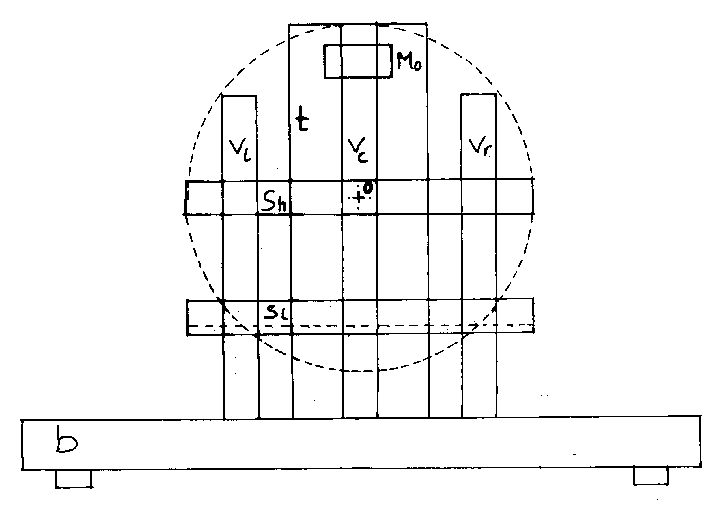 [6/2p] Rys. 9(c). [6/2p] Rys. 9(c).
[6/2e] Figure 9 (c): Telekinetic Influenzmaschine - frame.
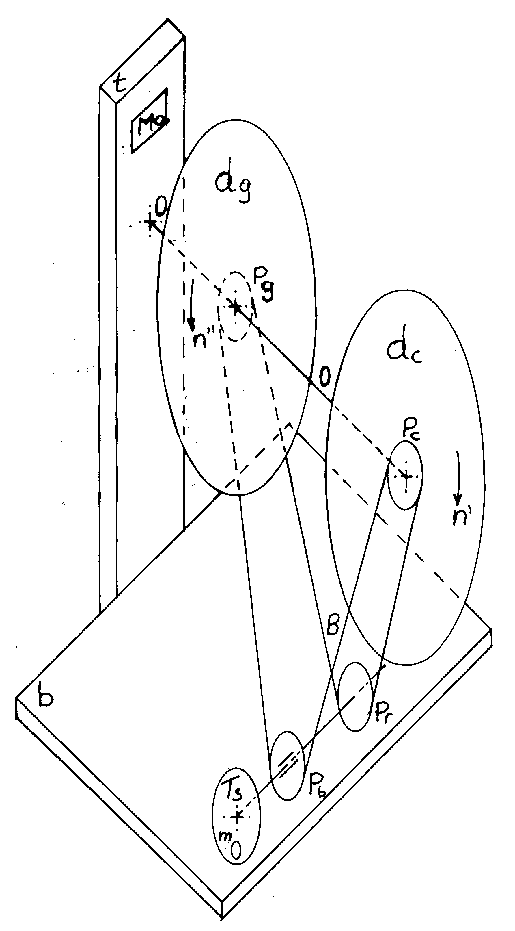 [6/2p] Rys. 9(d). [6/2p] Rys. 9(d).
[6/2e] Figure 9 (d): Telekinetic Influenzmaschine - kinematic diagram.
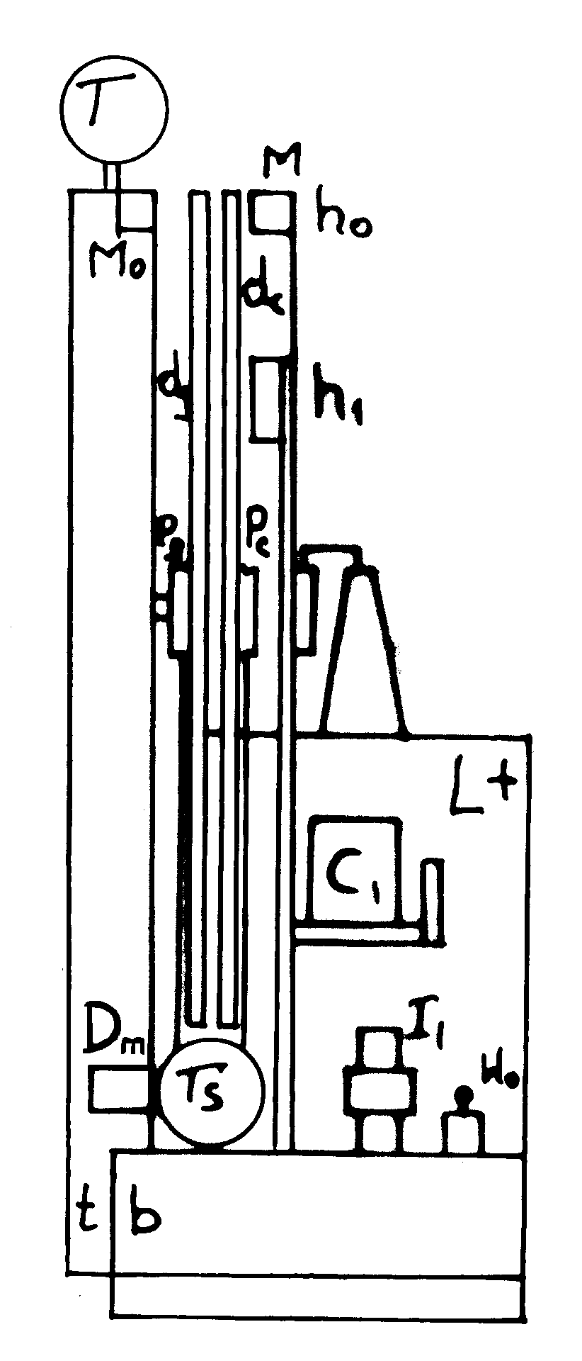 [6/2p] Rys. 9(e). [6/2p] Rys. 9(e).
[6/2e] Figure 9 (e): Telekinetic Influenzmaschine - side view (shown is the head of the telekinetic spindle).
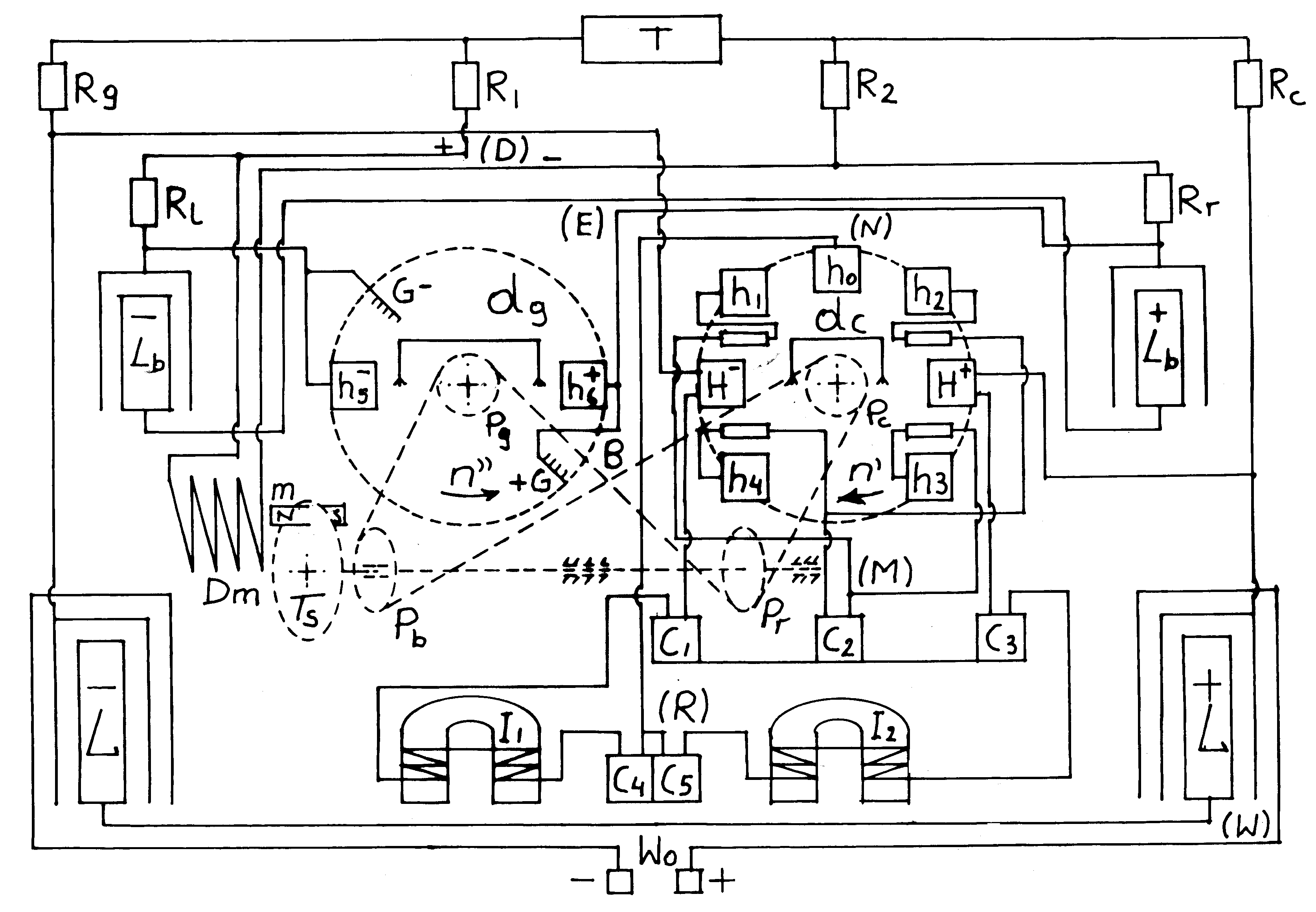 [6/2p] Rys. 10. [6/2p] Rys. 10.
[6/2e] Figure 10: The electrical wiring of Thesta-Distatica.
 [6/2p] Rys. 11(gora). [6/2p] Rys. 11(gora).
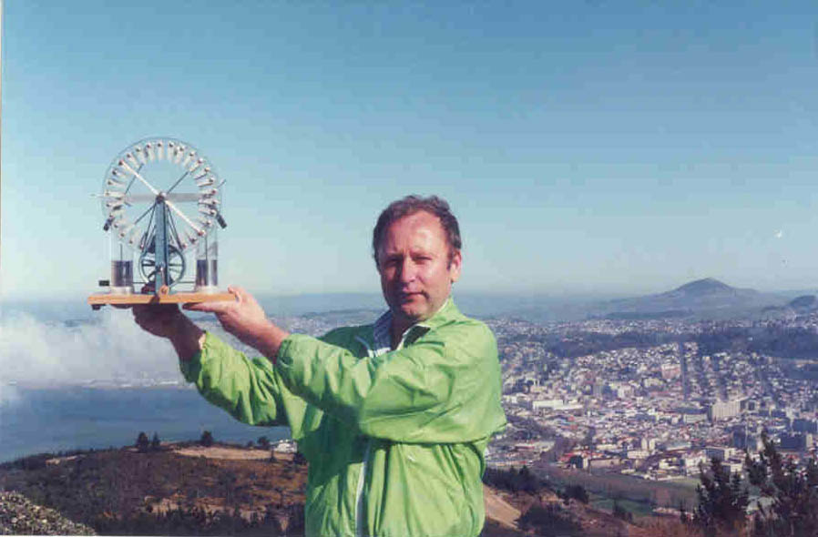
[6/2e] Figure 11 (high): Myself (Dr Jan Pajak) holding a Wimshurst electrostatic machine. The city below is Dunedin, New Zealand.
 [6/2p] Rys. 11(dol). [6/2p] Rys. 11(dol).
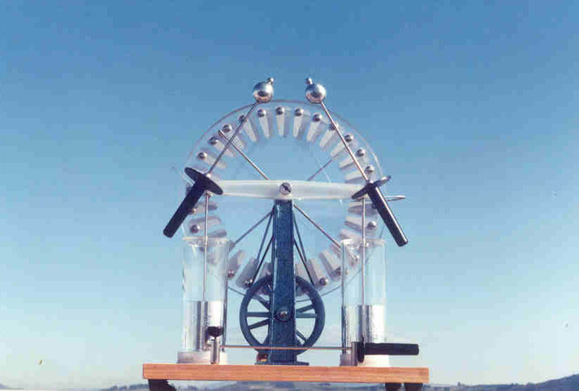
[6/2e] Figure 11 (low): A Wimshurst electrostatic machine - it is currently produced by a factory in Nysa, PPoland - for address see the text of [6/2].
 [6/2p] Rys. 12(A) Przekrój przez najmniejszy magnokraft typu K3 (ponieważ w podrozdziale P2 udowodniono formalnie że "UFO to już działający magnokraft", rysunek ten ilustruje również wykrój z najmniejszego UFO typu K3). [6/2p] Rys. 12(A) Przekrój przez najmniejszy magnokraft typu K3 (ponieważ w podrozdziale P2 udowodniono formalnie że "UFO to już działający magnokraft", rysunek ten ilustruje również wykrój z najmniejszego UFO typu K3).
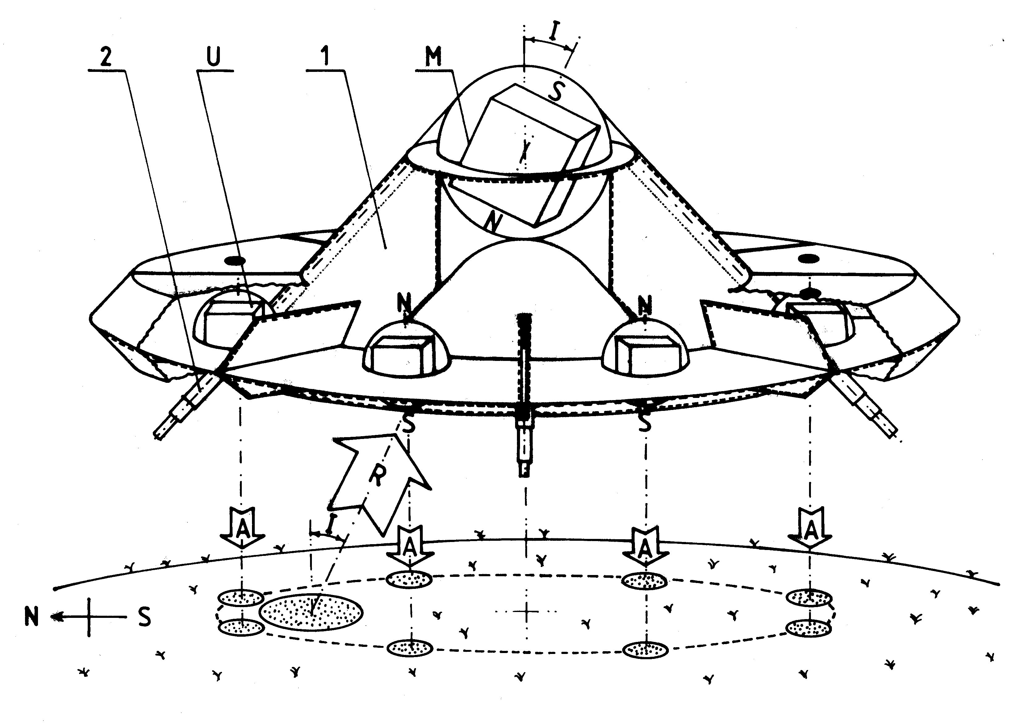
[6/2e] Figure 12 (A): The Magnocraft (and UFOs) type K3 cut-away view that shows the design and main features.
 [6/2p] Rys. 12(B) Wyglad boczny magnokraftu typu K3 (ponieważ w podrozdziale P2 udowodniono formalnie że "UFO to już działające magnokrafty", rysunek ten ilustruje również wygląd boczny najmniejszego UFO typu K3). [6/2p] Rys. 12(B) Wyglad boczny magnokraftu typu K3 (ponieważ w podrozdziale P2 udowodniono formalnie że "UFO to już działające magnokrafty", rysunek ten ilustruje również wygląd boczny najmniejszego UFO typu K3).
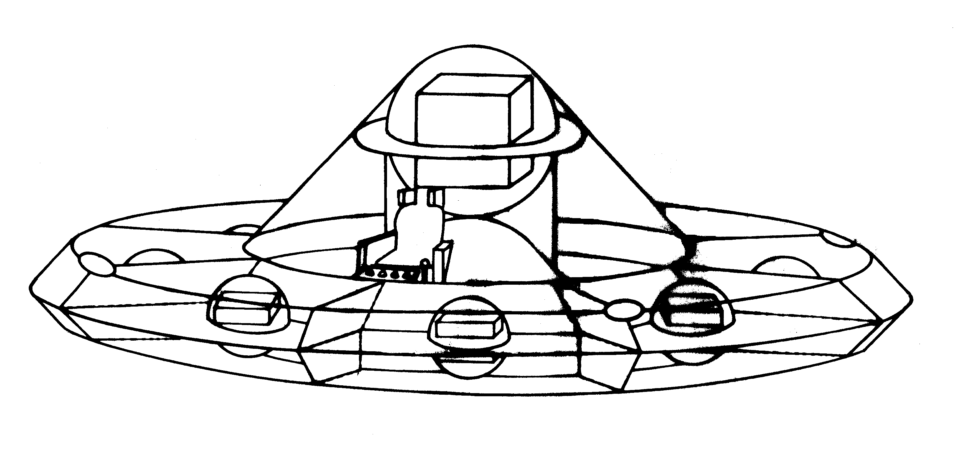
[6/2e] Figure 12 (B): A side view of the Magnocraft (and UFO) type K3.
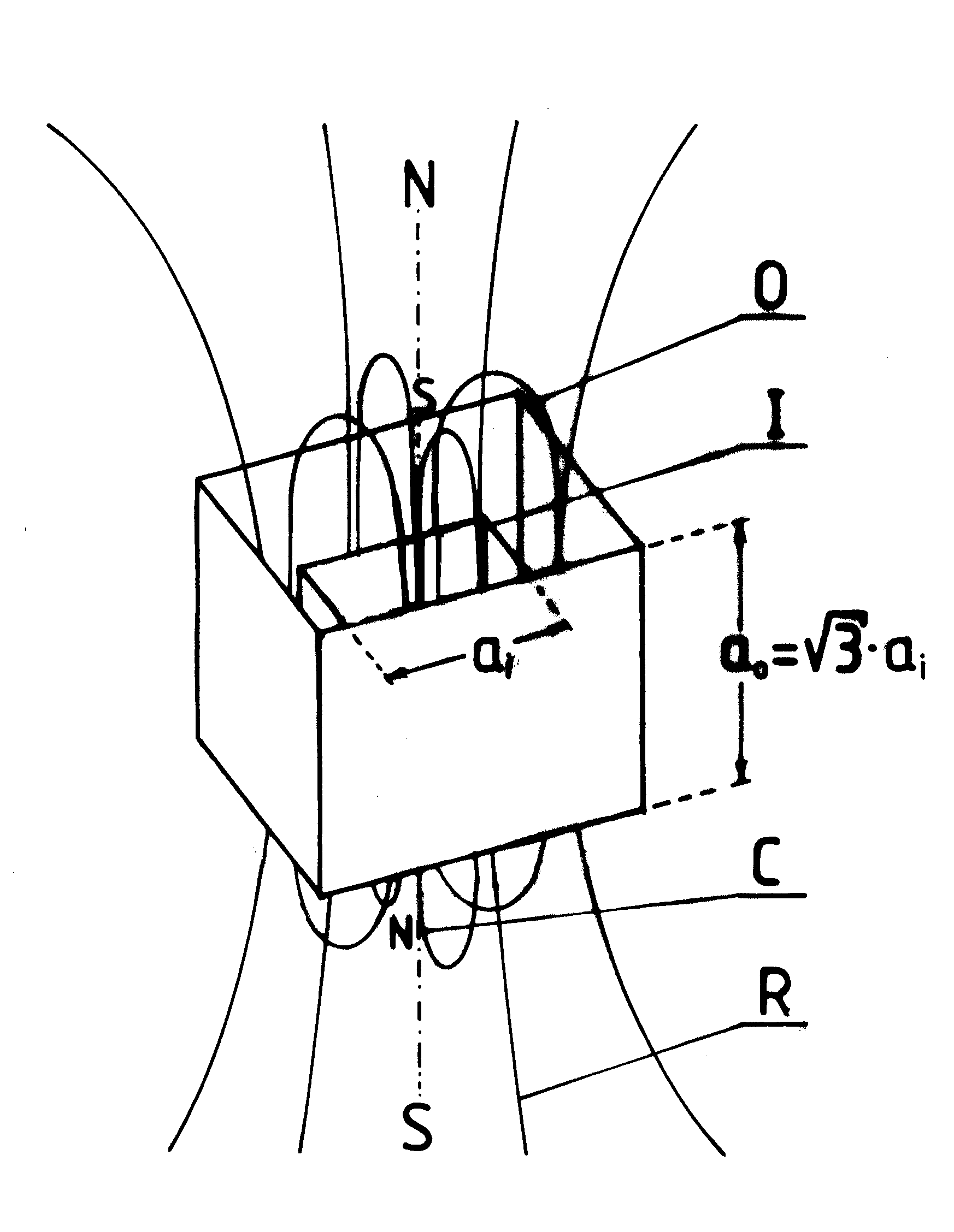 [6/2p] Rys. 12(C) Konstrukcja kapsuły dwukomorowej zestawionej z dwóch komór oscylacyjnych. Kapsuła ta jest sercem pędnika magnokraftu (oraz UFO - po szczegóły patrz rozdział S). [6/2p] Rys. 12(C) Konstrukcja kapsuły dwukomorowej zestawionej z dwóch komór oscylacyjnych. Kapsuła ta jest sercem pędnika magnokraftu (oraz UFO - po szczegóły patrz rozdział S).
[6/2e] Figure 12 (C): The twin-chamber capsule used as the propulsion system for the Magnocraft and UFOs.
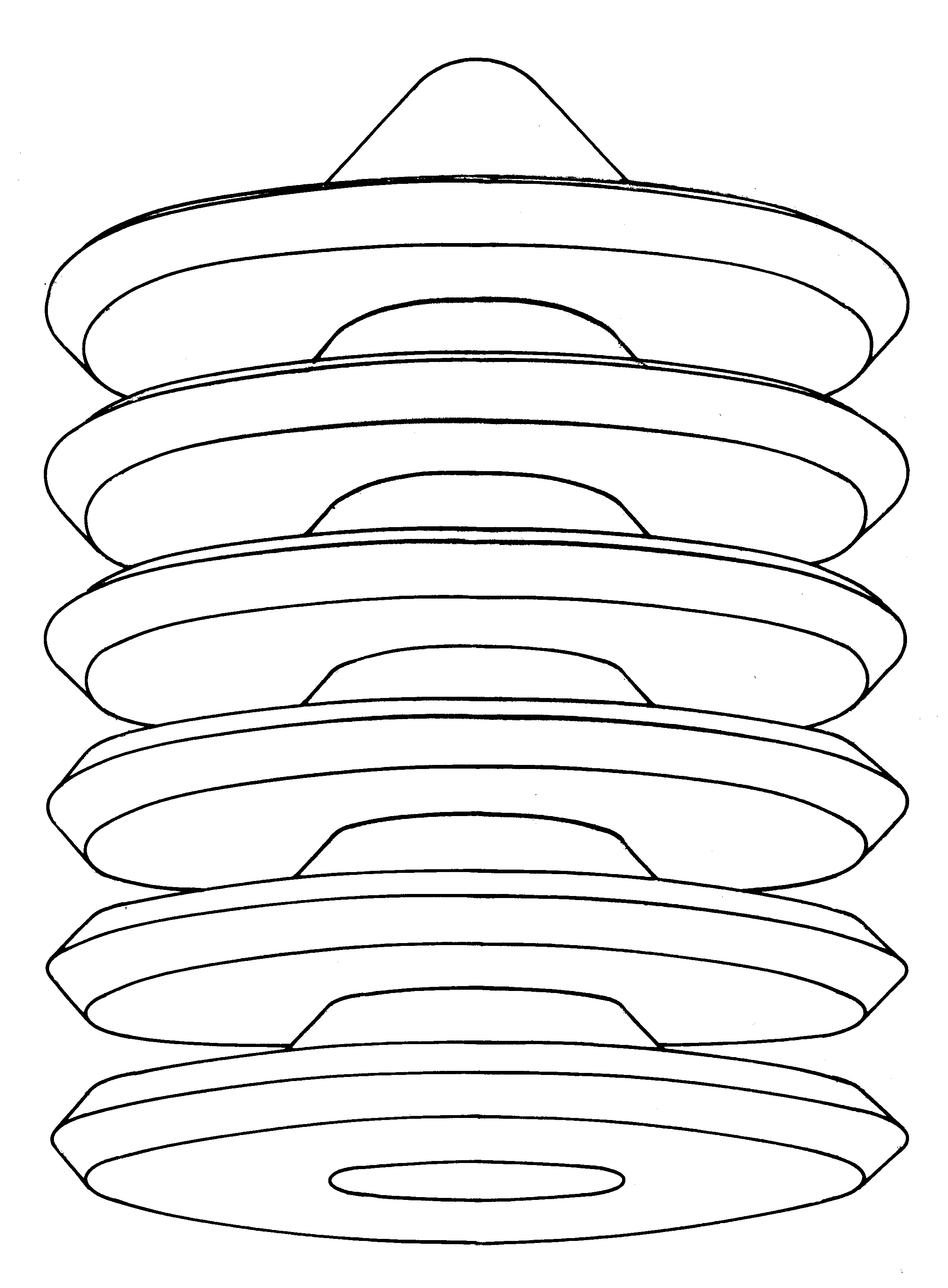 [6/2p] Rys. 13/1 Sześć podstawowych konfiguracji magnokraftów (pokazano je na przykładzie połączeń magnokraftów typu K3): konfiguracja (1) - latające cygaro. [6/2p] Rys. 13/1 Sześć podstawowych konfiguracji magnokraftów (pokazano je na przykładzie połączeń magnokraftów typu K3): konfiguracja (1) - latające cygaro.
[6/2e] Figure 13-#1: Flying complexes (cigar shaped)of UFOs and Magnocraft.
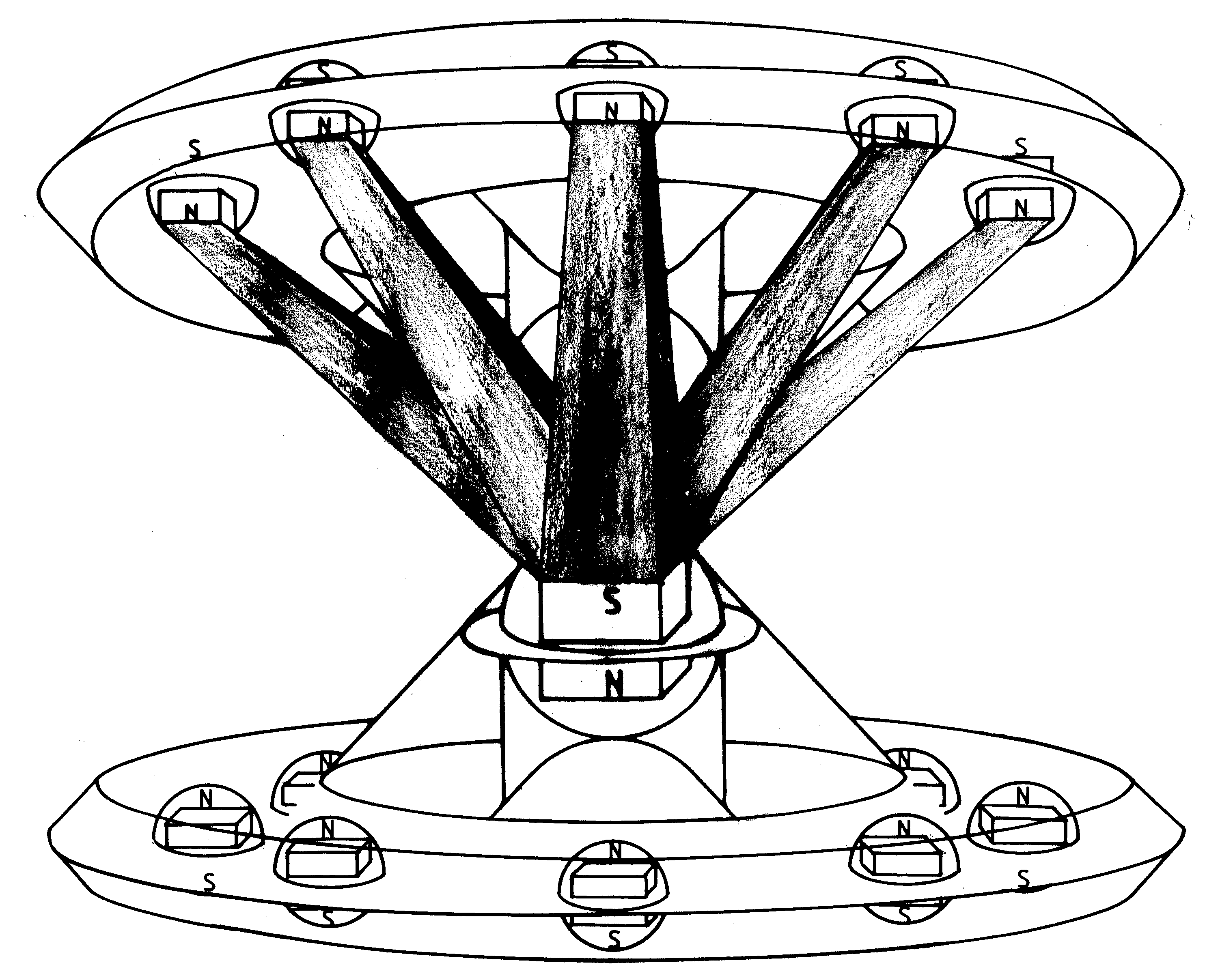 [6/2p] Rys. 13/2 Sześć podstawowych konfiguracji magnokraftów (pokazano je na przykładzie połączeń magnokraftów typu K3): konfiguracja (2) - zestaw semizespolony. [6/2p] Rys. 13/2 Sześć podstawowych konfiguracji magnokraftów (pokazano je na przykładzie połączeń magnokraftów typu K3): konfiguracja (2) - zestaw semizespolony.
[6/2e] Figure 13-#2: Semi-attached configuration.
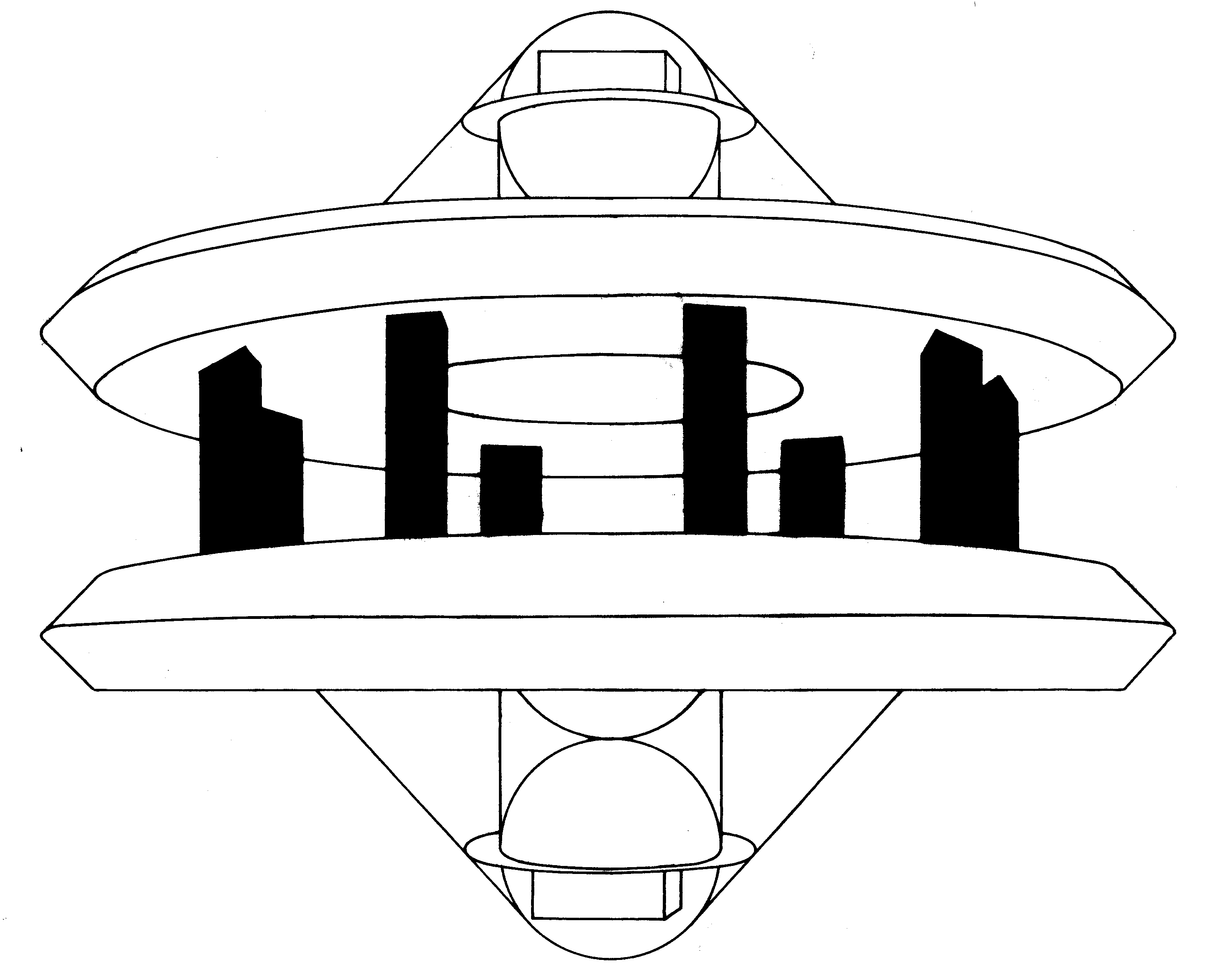 [6/2p] Rys. 13/3 Sześć podstawowych konfiguracji magnokraftów (pokazano je na przykładzie połączeń magnokraftów typu K3): konfiguracja (3) - zestaw niezespolony. [6/2p] Rys. 13/3 Sześć podstawowych konfiguracji magnokraftów (pokazano je na przykładzie połączeń magnokraftów typu K3): konfiguracja (3) - zestaw niezespolony.
[6/2e] Figure 13-#3: Detached configuration.
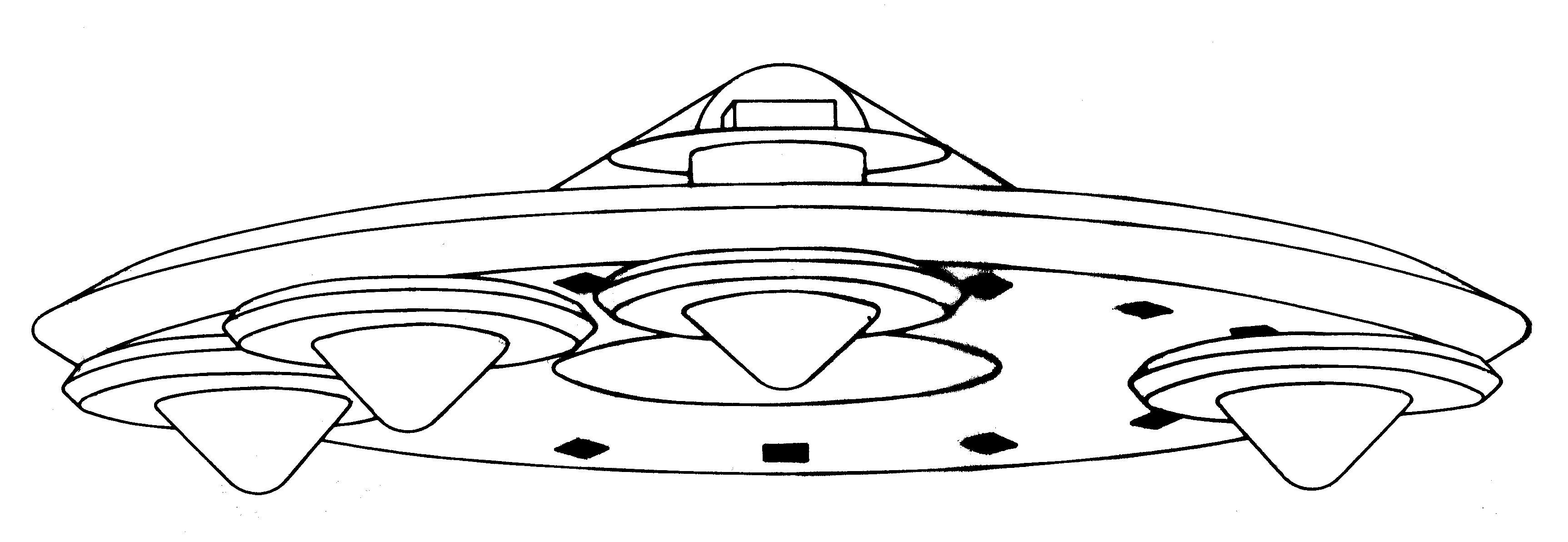 [6/2p] Rys. 13/4 Sześć podstawowych konfiguracji magnokraftów (pokazano je na przykładzie połączeń magnokraftów typu K3): konfiguracja (4) - układ podwieszony. [6/2p] Rys. 13/4 Sześć podstawowych konfiguracji magnokraftów (pokazano je na przykładzie połączeń magnokraftów typu K3): konfiguracja (4) - układ podwieszony.
[6/2e] Figure 13-#4: A carrier platform (a mother ship).
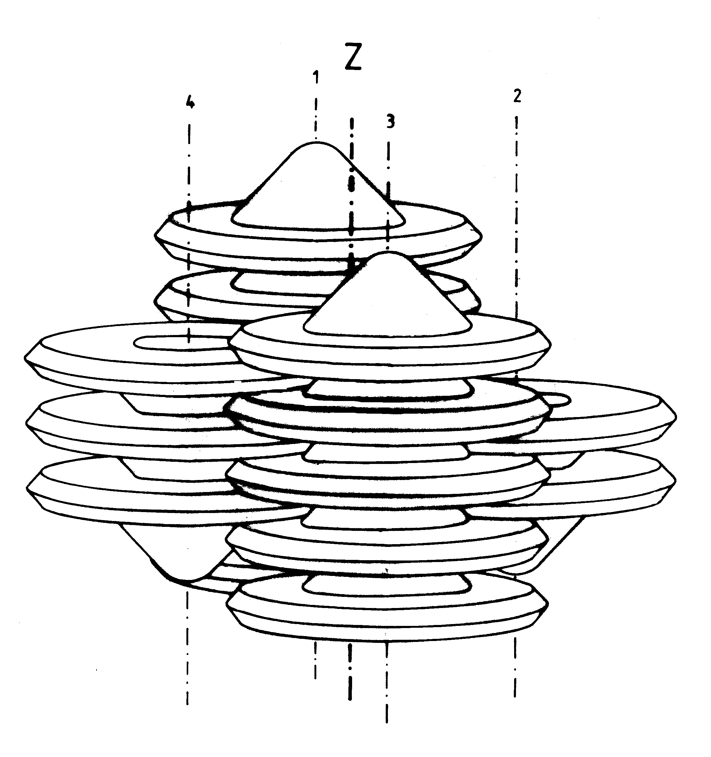 [6/2p] Rys. 13/5 Sześć podstawowych konfiguracji magnokraftów (pokazano je na przykładzie połączeń magnokraftów typu K3): konfiguracja (5) - latający system. [6/2p] Rys. 13/5 Sześć podstawowych konfiguracji magnokraftów (pokazano je na przykładzie połączeń magnokraftów typu K3): konfiguracja (5) - latający system.
[6/2e] Figure 13-#5: A flying system of UFOs and Magnocraft.
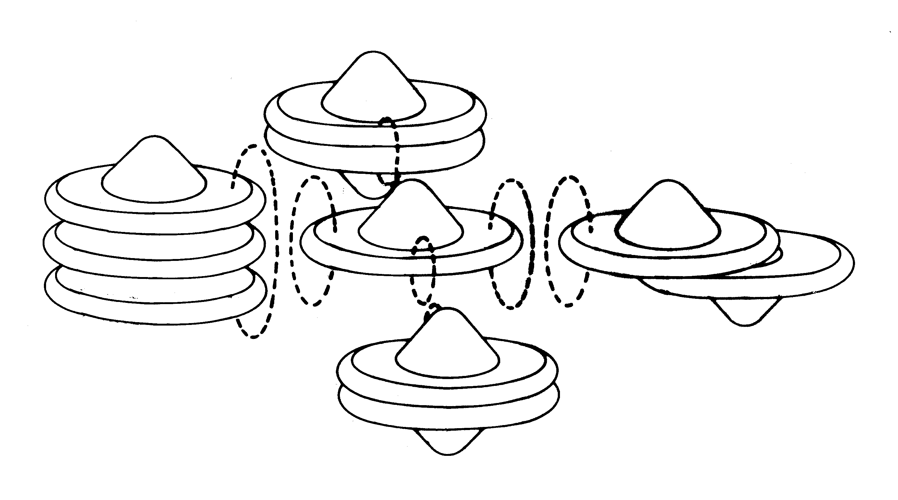 [6/2p] Rys. 13/6 Sześć podstawowych konfiguracji magnokraftów (pokazano je na przykładzie połączeń magnokraftów typu K3): konfiguracja (6) - latający kluster. [6/2p] Rys. 13/6 Sześć podstawowych konfiguracji magnokraftów (pokazano je na przykładzie połączeń magnokraftów typu K3): konfiguracja (6) - latający kluster.
[6/2e] Figure 13-#6: A flying cluster of several UFOs and Magnocraft.
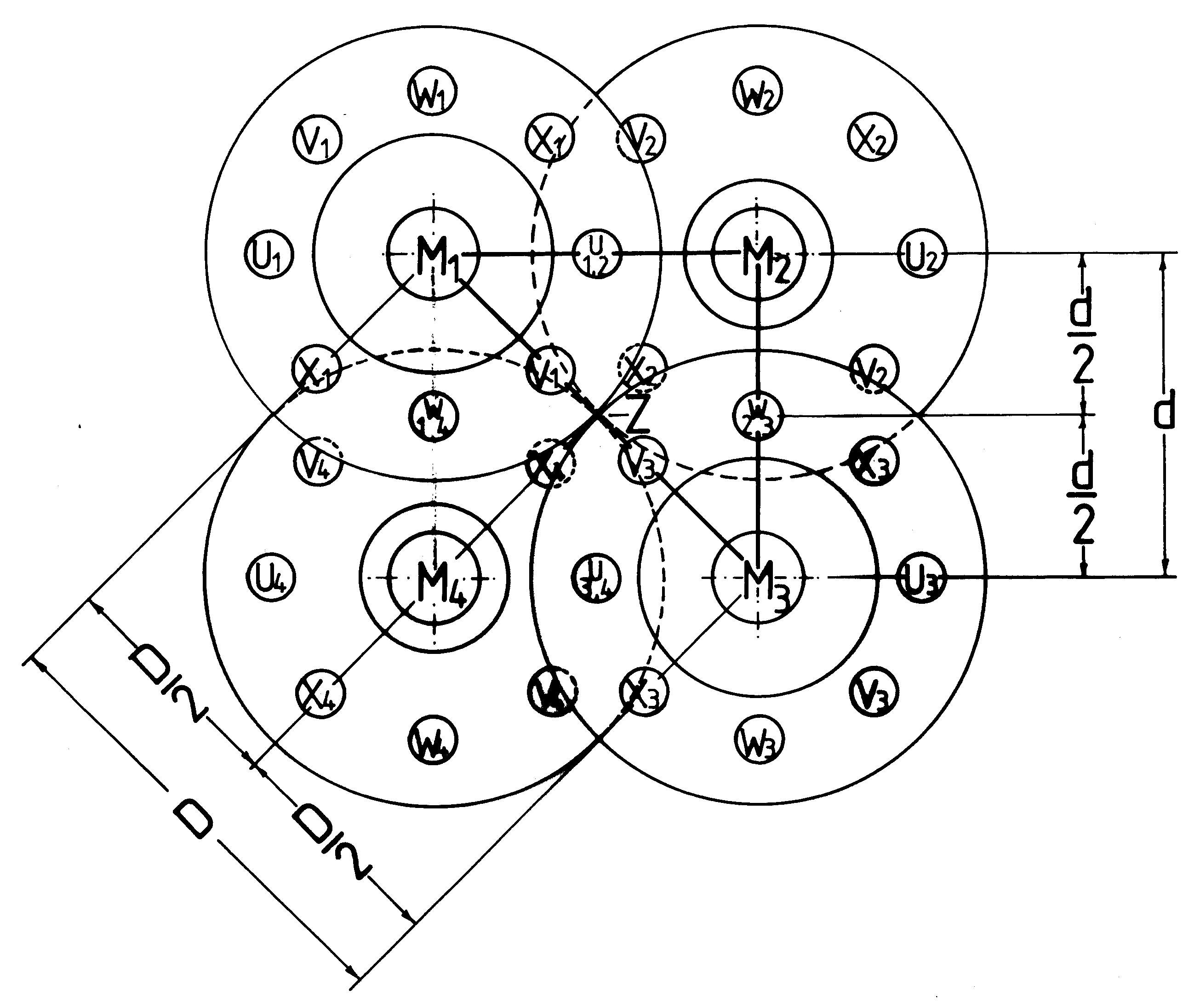 [6/2p] Rys. 14 Wygląd pojedyńczej celi latającego systemu magnokraftów (w tym przykładzie sprzężonej z magnokraftów typu K3). [6/2p] Rys. 14 Wygląd pojedyńczej celi latającego systemu magnokraftów (w tym przykładzie sprzężonej z magnokraftów typu K3).
[6/2e] Figure 14: An example of a flying cluster.
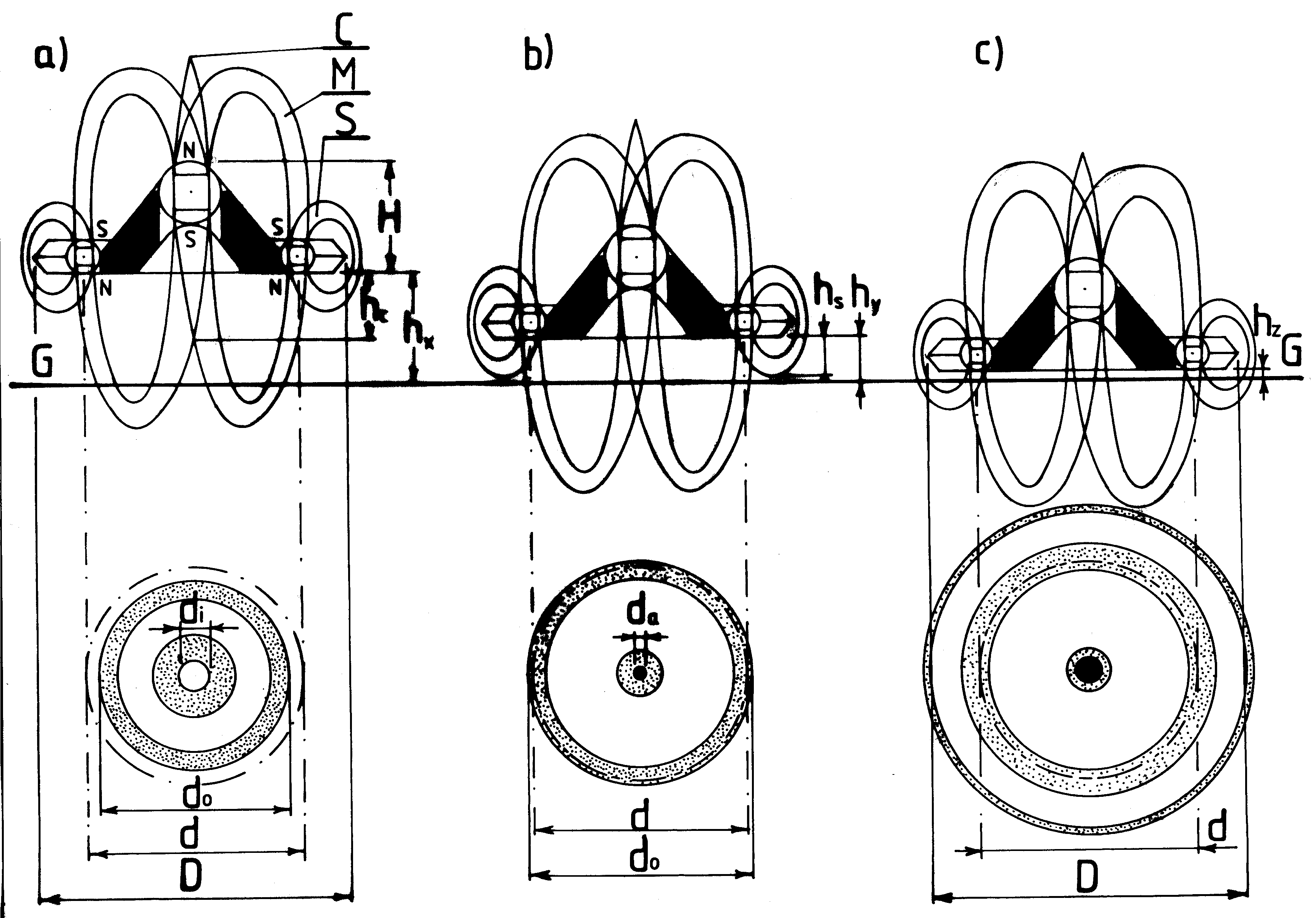 [6/2p] Rys. 15 Wpływ wysokości zawisania magnokraftu na kształt formowanego lądowiska. [6/2p] Rys. 15 Wpływ wysokości zawisania magnokraftu na kształt formowanego lądowiska.
[6/2e] Figure 15: Shapes of scorched marks left in grass by a single Magnocraft Magnocraft/UFO, depending on the height of hovering above the ground level.
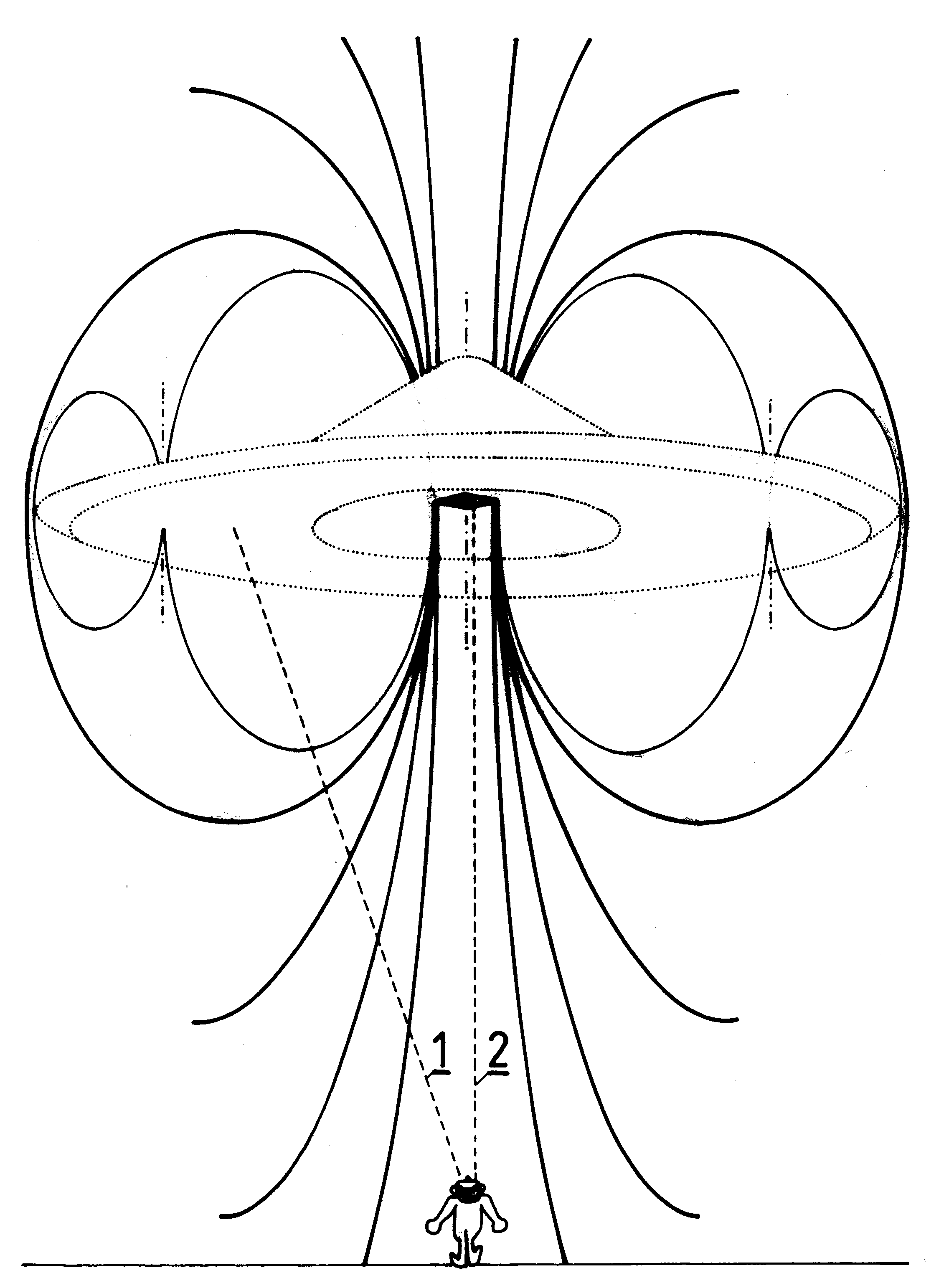 [6/2p] Rys. 16 Formowanie efektu soczewki magnetycznej przez pole magnokraftu. [6/2p] Rys. 16 Formowanie efektu soczewki magnetycznej przez pole magnokraftu.
[6/2e] Figure 16: A magnetic lens effect in Ascending Magnocraft, which causes that the vehicle dissapears, and only a twin-chamber capsule remains visible.
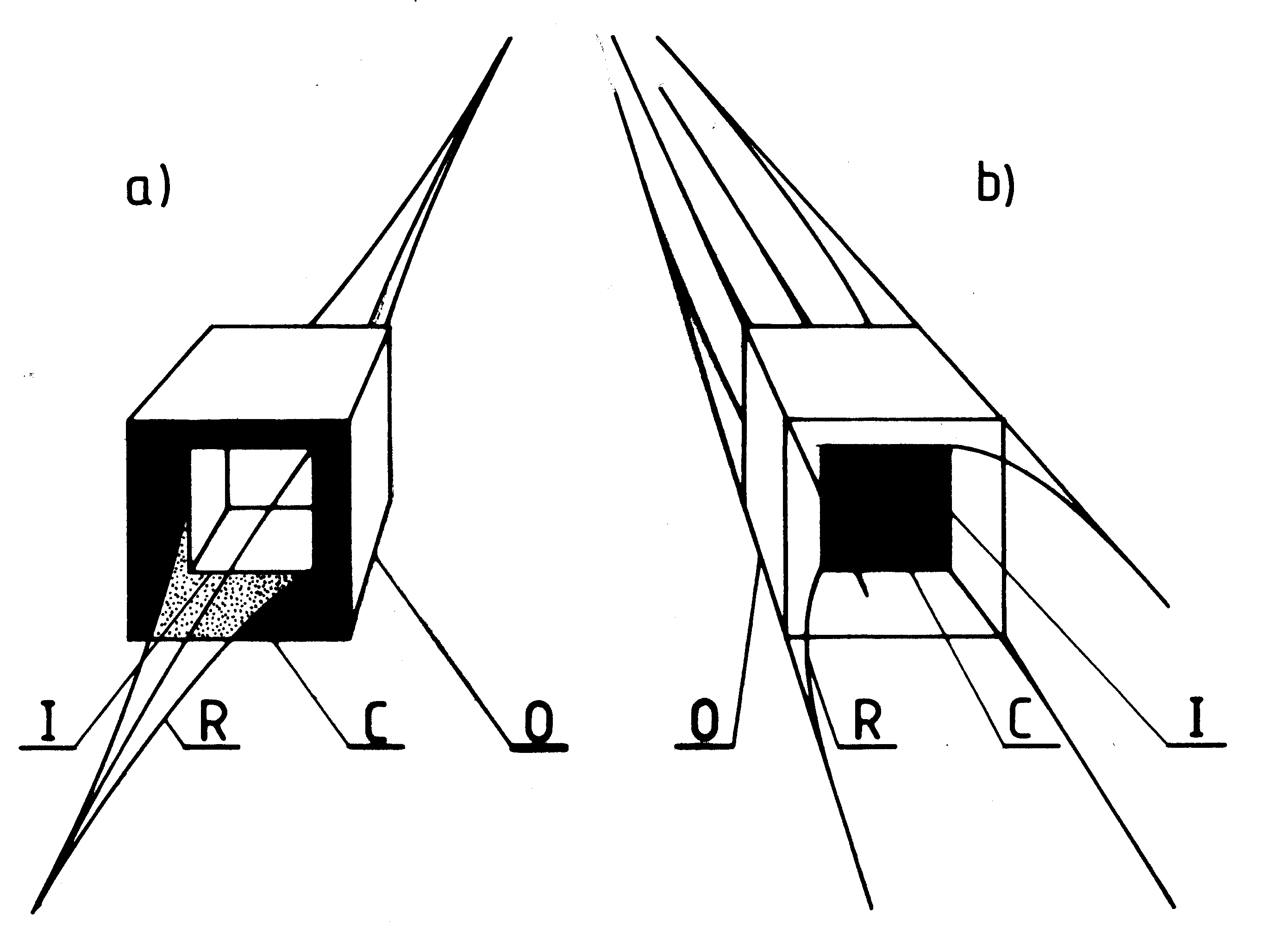 [6/2p] Rys. 17(ab) Wygląd kapsuł dwukomorowych magnokraftu pierwszej generacji w obu trybach działania (tj. (a) w dominacji strumienia wewnętrznego i (b) w dominacji strumienia zewnętrznego). [6/2p] Rys. 17(ab) Wygląd kapsuł dwukomorowych magnokraftu pierwszej generacji w obu trybach działania (tj. (a) w dominacji strumienia wewnętrznego i (b) w dominacji strumienia zewnętrznego).
[6/2e] Figure 17 (ab): Appearences of &qout;twin-chamber capsules" formed from two oscillatory chambers, depending which chamber dominates the magnetic field output.
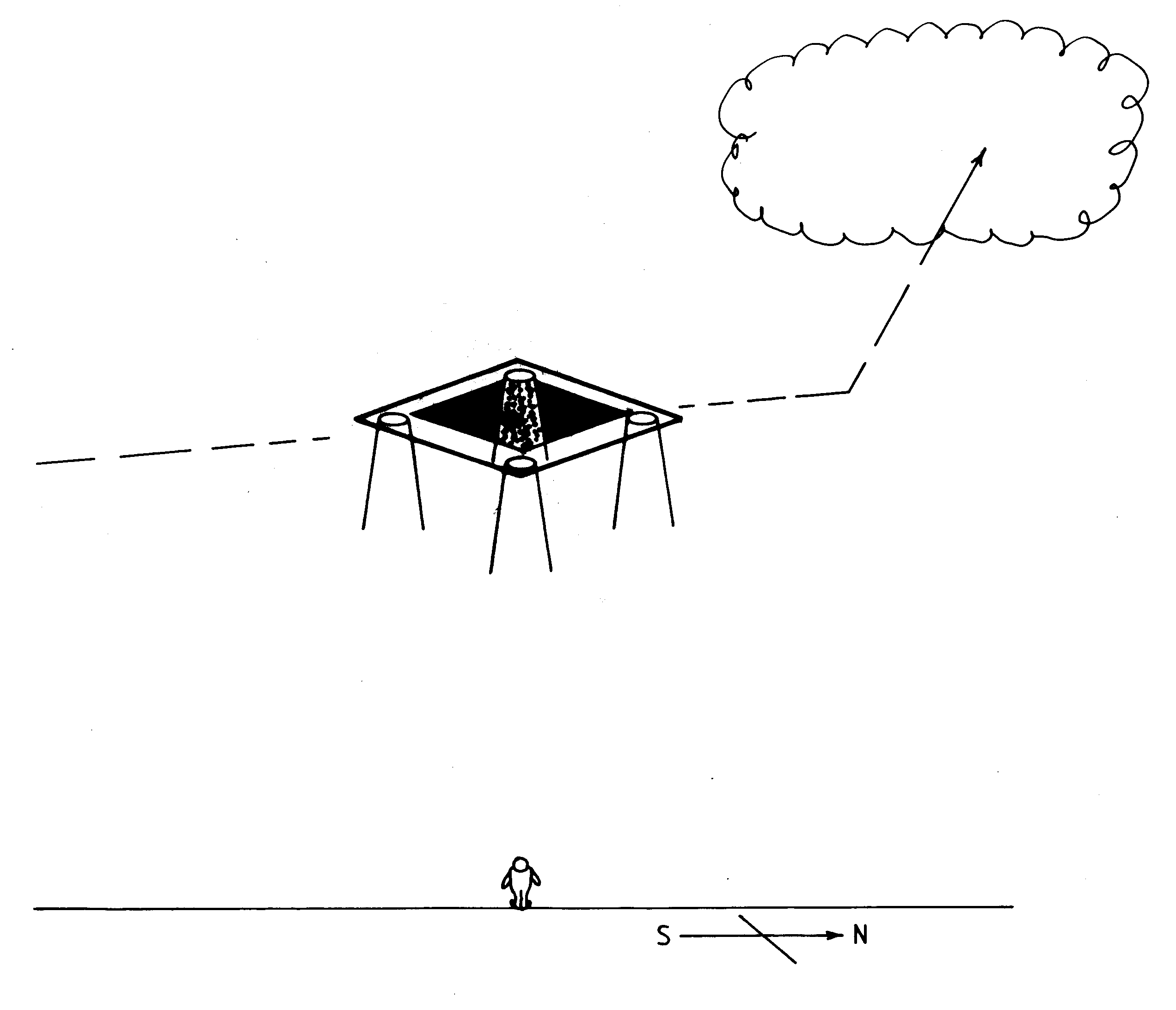 [6/2p] Rys. 17(c) Rysunek wyglądu kapsuły dwukomorowej we wznoszącym się UFO pierwszej generacji. [6/2p] Rys. 17(c) Rysunek wyglądu kapsuły dwukomorowej we wznoszącym się UFO pierwszej generacji.
[6/2e] Figure 17 (c): A drawing of the day-time twin chamber capsule visible in an ascending UFO, exactly as shown in parts (ab) - outer chamber flux domination.
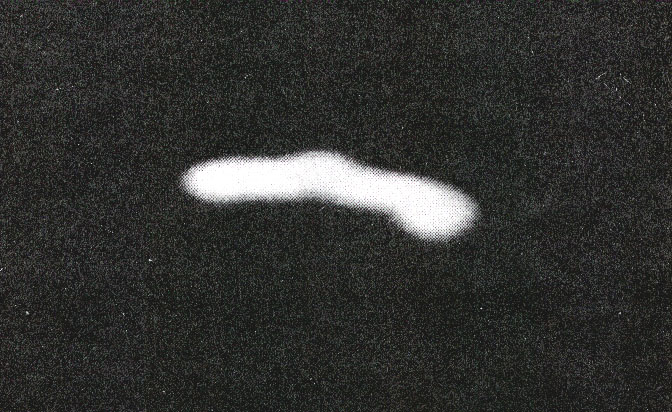 [6/2p] Rys. 17(d) Nocna fotografia kapsuły dwukomorowej wznoszącego się UFO pierwszej generacji. [6/2p] Rys. 17(d) Nocna fotografia kapsuły dwukomorowej wznoszącego się UFO pierwszej generacji.
[6/2e] Figure 17 (d): A night photo of a twin-chamber capsule from an ascending UFO (outer chamber flux domination).
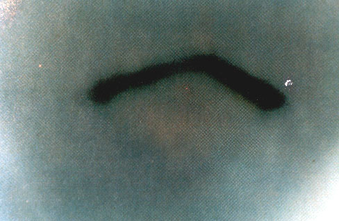 [6/2p] Rys. 17(e) Kolorowa fotografia kapsuły dwukomorowej u wznoszącego się UFO pierwszej generacji, oglądanej we dnie. [6/2p] Rys. 17(e) Kolorowa fotografia kapsuły dwukomorowej u wznoszącego się UFO pierwszej generacji, oglądanej we dnie.
[6/2e] Figure 17 (e): A day-time photograph of a UFO twin chamber capsule that operates with inner chamber flux domination.
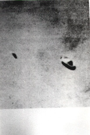 [6/2p] Rys. 18 . [6/2p] Rys. 18 .
[6/2e] Figure 18: Comparison of shapes of K3 type UFO to a K3 type Magnocraft.
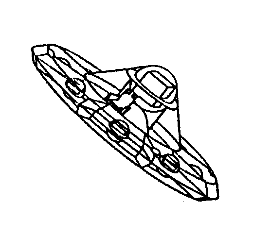 [6/2p] Rys. 18(obramowanie). [6/2p] Rys. 18(obramowanie).
[6/2e] Figure 18 (framed): A side view of the K3 type Magnocraft in the same position as that UFO.
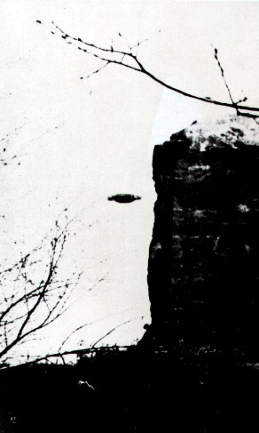 [6/2p] Rys. 19(a). [6/2p] Rys. 19(a).
[6/2e] Figure 19 (a): The Thorns photo of a spherical complex magnetically coupled from two UFOs of K6 type.
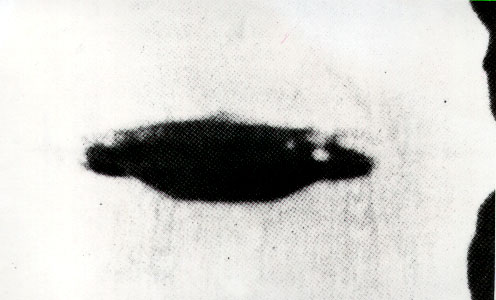 [6/2p] Rys. 19(b). [6/2p] Rys. 19(b).
[6/2e] Figure 19 (b): The enlargement of the UFO from Thorns photograph.
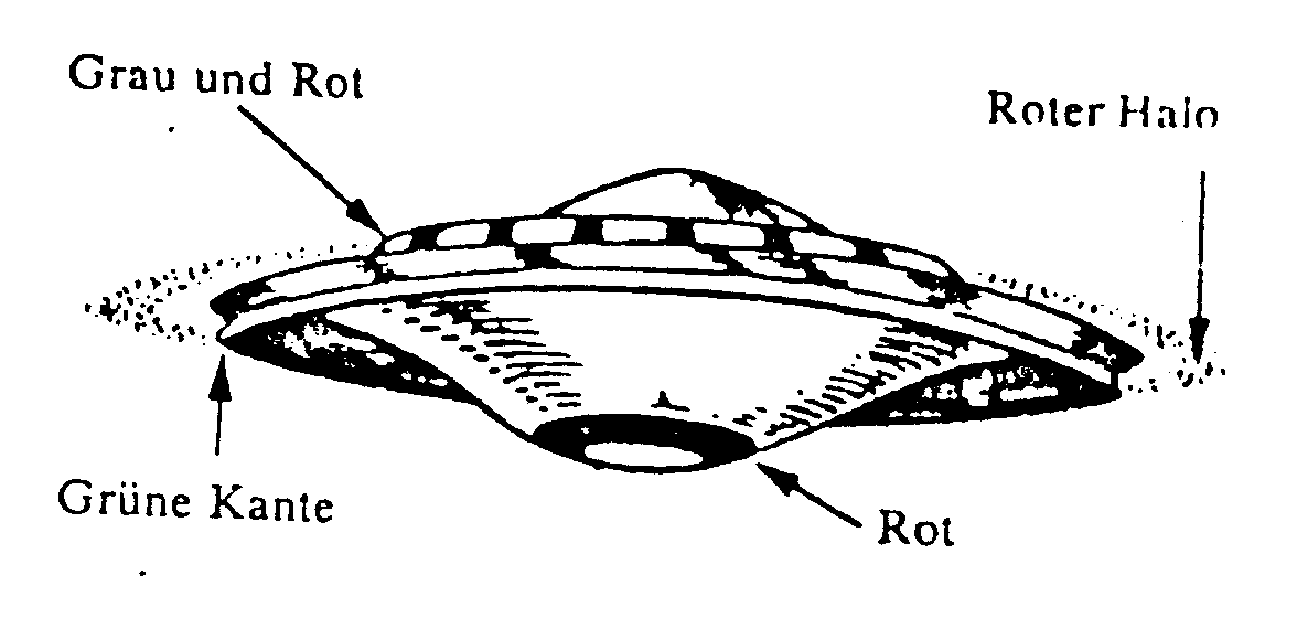 [6/2p] Rys. 19(c). [6/2p] Rys. 19(c).
[6/2e] Figure 19 (c): The shape of the Thorns UFO in GICOFF reconstruction. (See Figure K2 (ab) to compare this UFO with a sperical complex of two Magnocraft.)
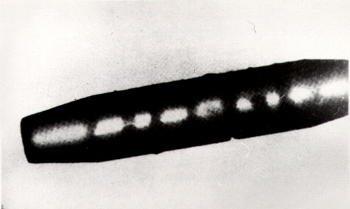 [6/2p] Rys. 20(a). [6/2p] Rys. 20(a).
[6/2e] Figure 20 (a): Cigar-shaped UFO from Palomar Gardens, 1952.
 [6/2p] Rys. 20(b). [6/2p] Rys. 20(b).
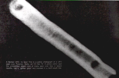
[6/2e] Figure 20 (b): Cigar-shaped UFO from Palermo, Sicily, 1978.
 [6/2p] Rys. 20(c). [6/2p] Rys. 20(c).
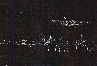
[6/2e] Figure 20 (c): Cigar-shaped UFO above New York, 1950.
 [6/2p] Rys. 20(d). [6/2p] Rys. 20(d).
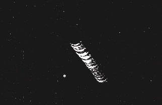
[6/2e] Figure 20 (d): An enlargement of the cigar-shaped UFO from New York shown in part (c).
 [6/2p] Rys. 21(A). [6/2p] Rys. 21(A).
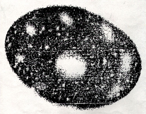
[6/2e] Figure 21 (A): The location of glowing outlets from propulsors in K3 type Magnocraft seen from below.
 [6/2p] Rys. 21(B). [6/2p] Rys. 21(B).
[6/2e] Figure 21 (B): A photo of outlets from a UFO type K3, photographed from below.
 [6/2p] Rys. 22(a). [6/2p] Rys. 22(a).
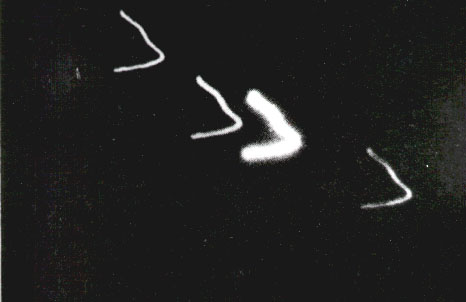
[6/2e] Figure 22 (a): Photo of flashes of the air ionised by pulsating magnetic field from a very fast moving UFO (Chamberlain).
 [6/2p] Rys. 22(b). [6/2p] Rys. 22(b).
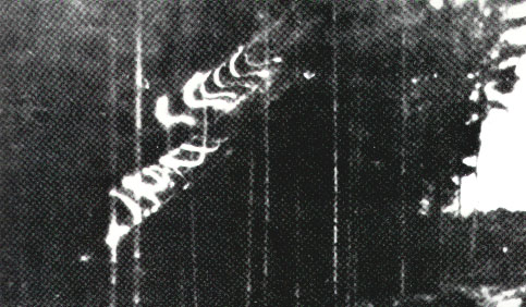
[6/2e] Figure 22 (b): Flashes from the air ionised by magnetic circuits of a UFO photographed by Karl Maier, 1962.
 [6/2p] Rys. 23(AB). [6/2p] Rys. 23(AB).
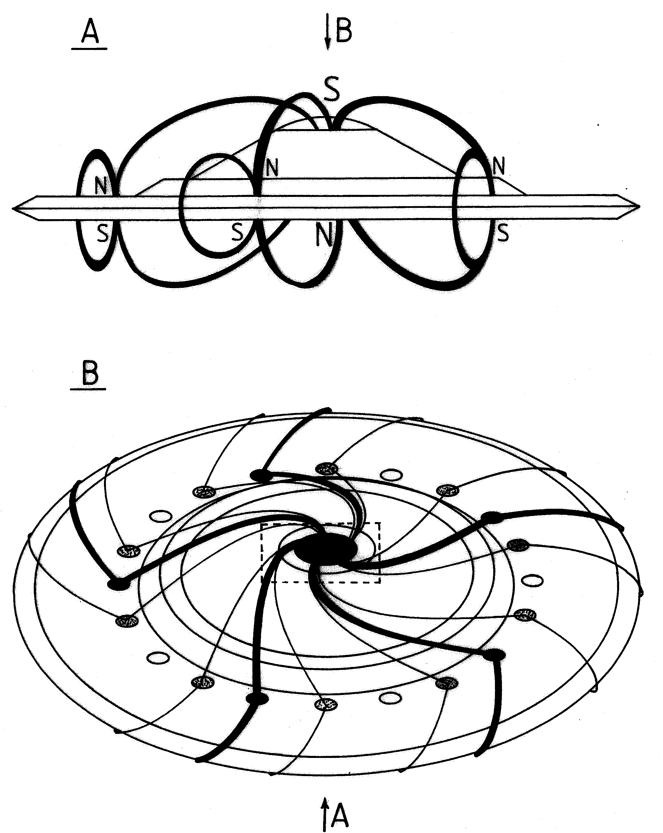
[6/2e] Figure 23 (AB): The course of magnetic circuits formed by a Magnocraft type K6 (these circuits are capable of ioniseg the air).
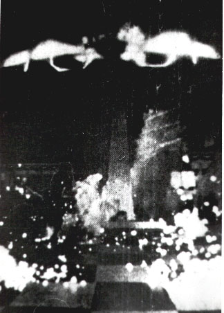 [6/2p] Rys. 23(C). [6/2p] Rys. 23(C).
[6/2e] Figure 23 (C): A side photograph of a UFO type K6 showing the glowing air ionised by magnetic circuits.
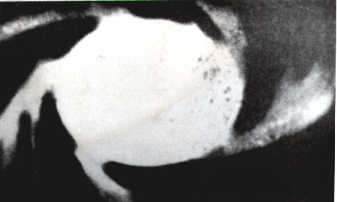 [6/2p] Rys. 23(D). [6/2p] Rys. 23(D).
[6/2e] Figure 23 (D): A fragment of a UFO type K6 spinning magnetic circuits photographed from below.
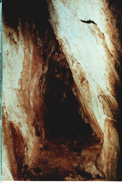 [6/2p] Rys. 24/1. [6/2p] Rys. 24/1.
[6/2e] Figure 24-#1: The tunnel Morona-Santiago in Equador also evaporated by a UFO.
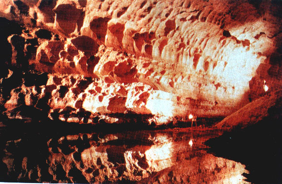 [6/2p] Rys. 24/2. [6/2p] Rys. 24/2.
[6/2e] Figure 24-#2: The Cocklebiddy Cave in Australia evaporated by UFOs.
 [6/2p] Rys. 24/3. [6/2p] Rys. 24/3.
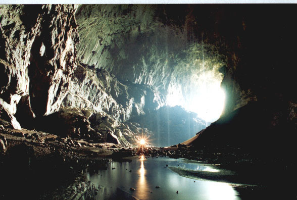
[6/2e] Figure 24-#3: The Deer Cave in Borneor evaporated in rocks by UFOs type K8.
 [6/2p] Rys. 24/4. [6/2p] Rys. 24/4.
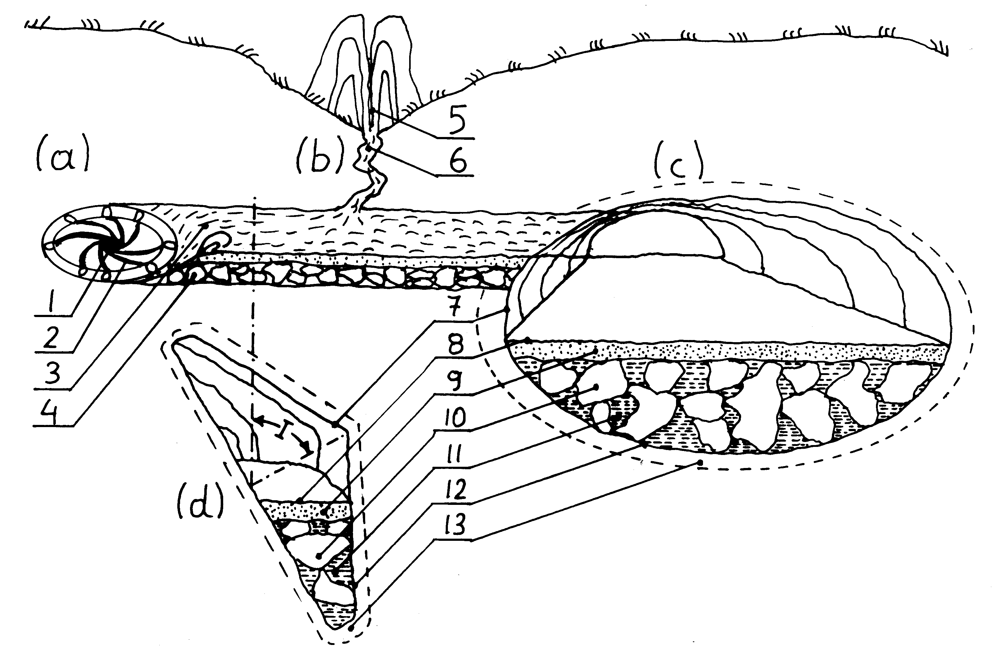
[6/2e] Figure 24-#4: The illustration of pinciples of forming underground tunnels by UFOs.
 [6/2p] Rys. 25. [6/2p] Rys. 25.
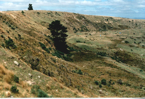
[6/2e] Figure 25: An eastern section of the Tapanui Crater where UFOs exploded in 1178 AD.
 [6/2p] Rys. 26. [6/2p] Rys. 26.
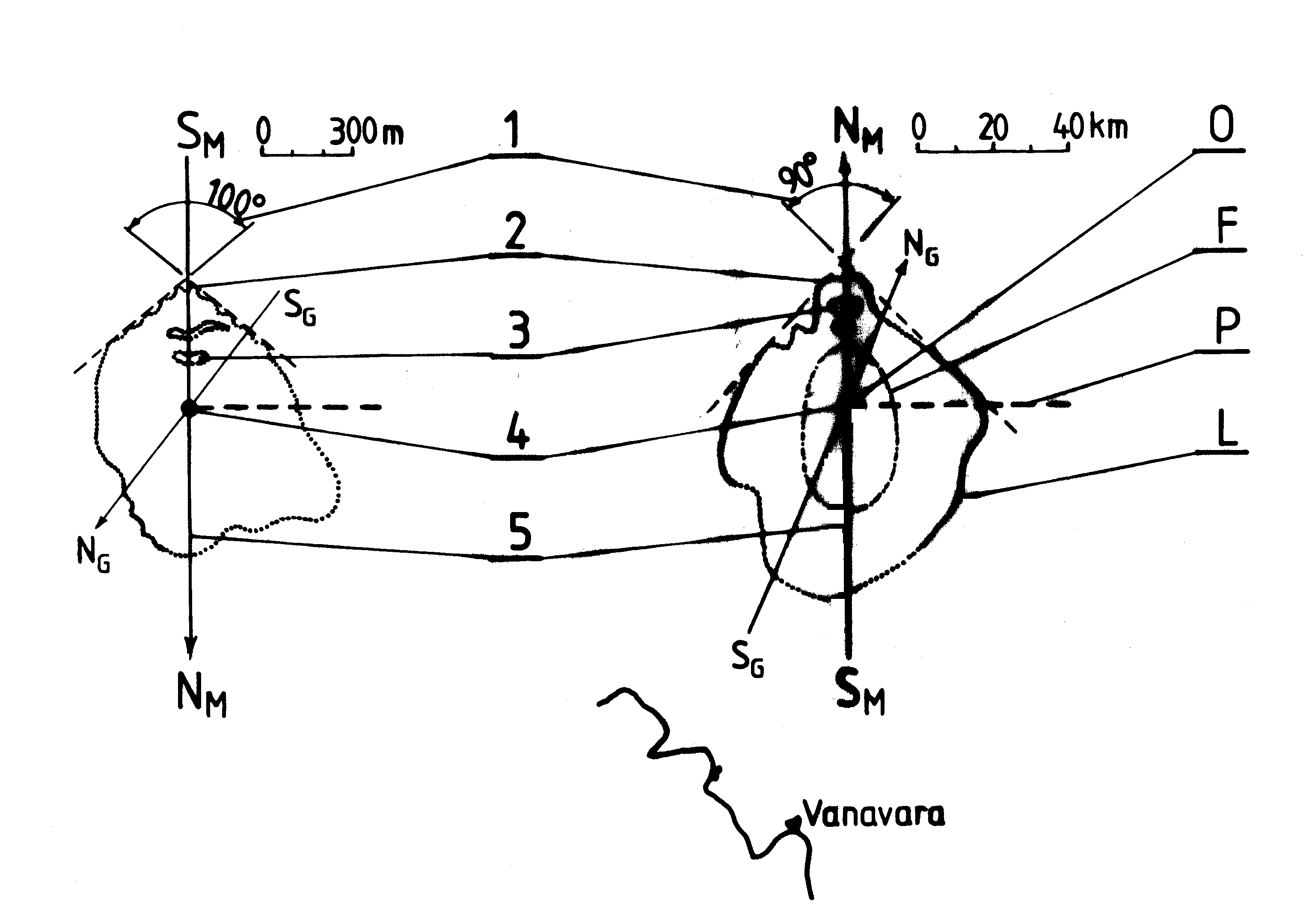
[6/2e] Figure 26: Similarities between Tunguska and Tapanui UFO explosion sites.
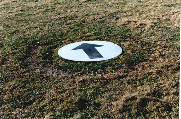 [6/2p] Rys. 27(A). [6/2p] Rys. 27(A).
[6/2e] Figure 27 (A): A photo of a UFO landing composed of two concentric rings.
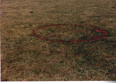 [6/2p] Rys. 27(B). [6/2p] Rys. 27(B).
[6/2e] Figure 27 (B): A UFO landing composed of one ring and a central scorching.
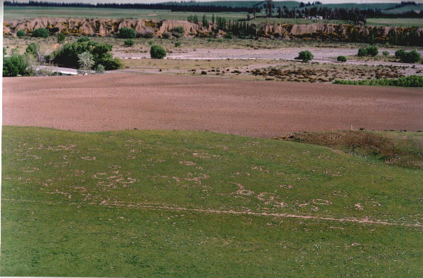 [6/2p] Rys. 27(C). [6/2p] Rys. 27(C).
[6/2e] Figure 27 (C): A Double rings formed on sides of landed UFOs.
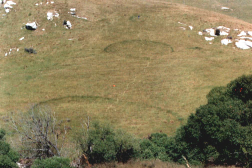 [6/2p] Rys. 27(D). [6/2p] Rys. 27(D).
[6/2e] Figure 27 (D): Three UFO landings which illustrate the principle of binary progression in dimensions of subsequent types of UFOs (because of this progression, each higher type of UFO is twice as big as the previous type).
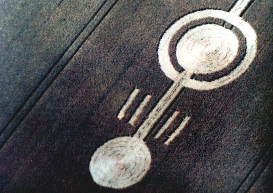 [6/2p] Rys. 28(a). [6/2p] Rys. 28(a).
[6/2e] Figure 28 (a): English crop circles formed during landing of a flying cluster of two UFOs type K6 (the appearence and principle of magnetic couplic for this cluster is shown in Figure 14).
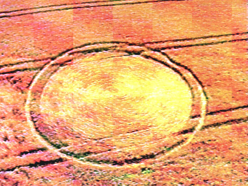 [6/2p] Rys. 28(b-gora). [6/2p] Rys. 28(b-gora).
[6/2e] Figure 28 (b-high): A cop circle from Ashurton, New Zealand, formed in February 1992.
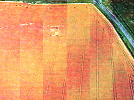 [6/2p] Rys. 28(b-dol). [6/2p] Rys. 28(b-dol).
[6/2e] Figure 28 (b-low): An aerial photograph of that crop circle from Ashburton in New Zealand.
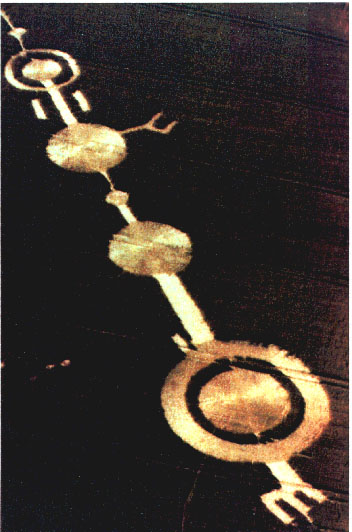 [6/2p] Rys. 28(c). [6/2p] Rys. 28(c).
[6/2e] Figure 28 (c): A landing of a liner cluser of several UFOs in English crops (see also Figure 14).
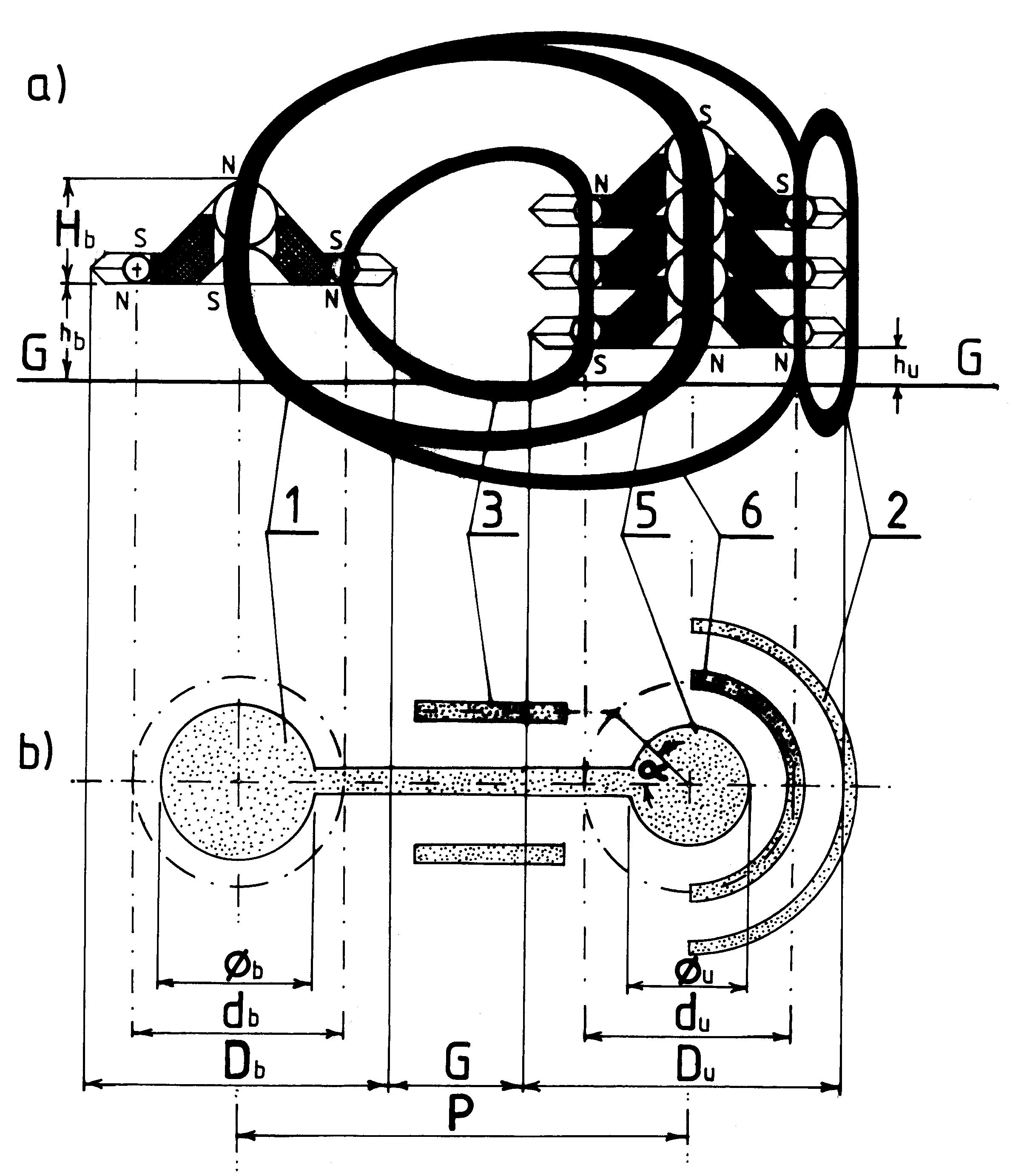 [6/2p] Rys. 29. [6/2p] Rys. 29.
[6/2e] Figure 29: Mathematical relationships that can be found in crop circles - means in landins of UFOs in crops.
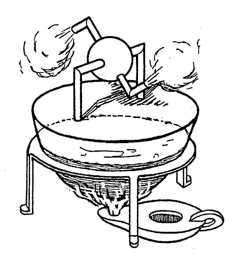 [6/2p] Rys. 30(a). [6/2p] Rys. 30(a).
[6/2e] Figure 30 (a): The aeolipile build by Hero of Alexandira around 130 BC. It took almost two thousands years to build a steam turbine which works on a similar principle.
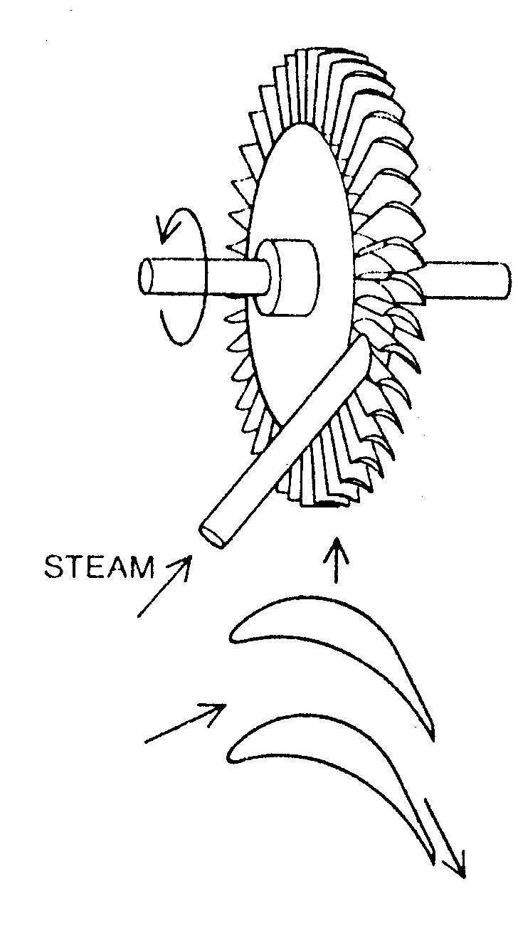 [6/2p] Rys. 30(b). [6/2p] Rys. 30(b).
[6/2e] Figure 30 (b): Steam turbine by C.A. Parsons, 1884.
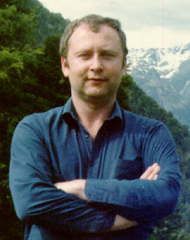 [6/2p] Rys. Dr Jan Pajak. [6/2p] Rys. Dr Jan Pajak.
[6/2e] The author: Photograph of the author of this monograph [6/2e].
Instructions:
(1) To download any volume, just click
on the underlined name of this volume, and then save this publication in
your own computer.
(2) After you finish visiting illustrations click BACK on the top-left of the
screen in order to return to this Web page.
(3) Because of the strict limit imposed by this server on sizes of uploaded files,
the WORD (*.doc) version of [6e] needed to be split into several separate files.
(4) Note that in spite of the size restrictions, still some files are quite large.
Thus when lines are busy it may take several minutes to download them.
(5) English text contained in the text files (*.doc and *.zip) is prepared to be
handled with the WORD wordprocessor.
(6) Polish text contained in the compressed text files (*.zip) is prepared to be
handled with the "Word Perfect version 5.1" wordprocessor (which uses Polish letters).
If such files are input by the English-oriented WORD, than in place of Polish letters
underscore symbols "_" will appear.
(7) In order to unzip back into the WORD format all files that are compressed into
the *.ZIP format, you need to go through a standard unzipping routine. In case you are
not familiar with it, I repeat this rountine for WINDOWS 2000.
(a) You start from downloading a given *zip file to your computer by clicking onto it
in this Web page.
Then (b) you need to open the program named WINDOWS EXPLORER that your probably have
in your computer (click: START/ PROGRAMS/ ACCESORIES/ WINDOW EXPLORER), find with this
program your *.zip file, and then right click on this *.zip file with your mouse,
so that the Menu of unzipping commands unfolds.
Then (c) you need to choose and left click with your mouse at any of the EXTRACT commands,
e.g. the EXTRACT TO command.
Then (d) You need to refresh your WINDOW EXPLORER, e.g. by temporary shifting it into
other directory and then returning back, so that the file that you just unzipped become
seen by it.
Finally (e) you need to shift inside of the directory which bears the name of the unzipped
file, and then inside of this directly double click on the unzipped *.doc file in order
to see the content of this file in WORD.
Note that there also various other unzipping programs, apart from the WINDOWOS EXPLORER,
e.g. the program named POWER ARCHIVER which you can download from the
www.powerarchiver.com.
For these other programs just follow their own routines of unzipping.
Have interesting reading about free energy devices.
|